Burner specifications and settings, Weil-mclain 88 water and steam boilers — series 2, Table 1 – Weil-McLain RLS User Manual
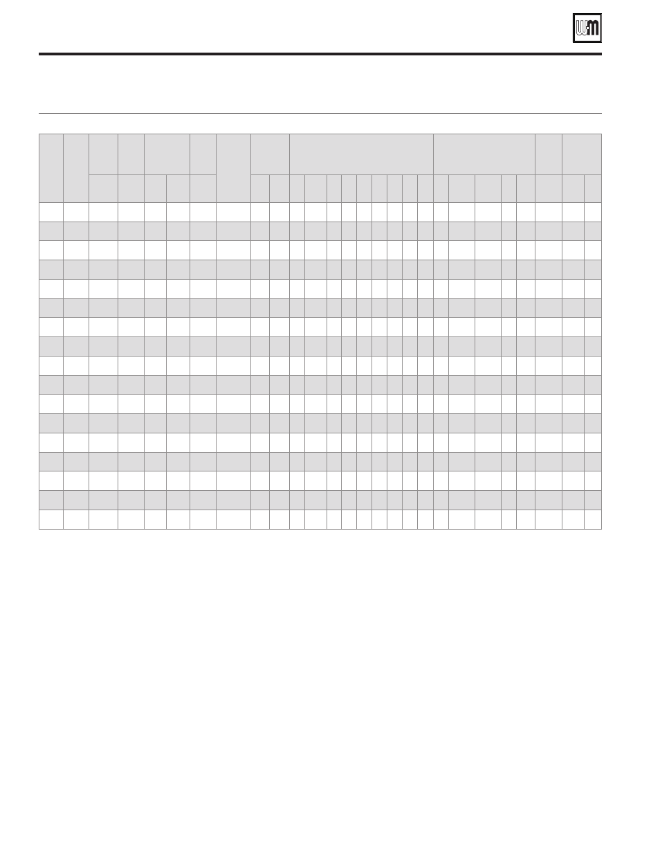
Page 2: For gas, light oil, & gas/light oil-fired burners, Burner data — #2 fuel oil/natural gas — modulating
Weil-McLain 88 Water and Steam Boilers — Series 2 —
For Gas, Light Oil, & Gas/Light Oil-Fired Burners
2
Part No. 550-142-023/0508
Burner data — #2 Fuel oil/Natural gas — Modulating
Table 1
Boiler
Model
Number
Burner
Model
Number
Pressure
Drop Thru
Gas Train
Manifold
Pressure
Gas Pressure
Required at
Gas Control
Inlet
Gas Pilot
Pressure
Combustion
Head
Setting
Combustion
Air
Indications
Servo Motor Cam
Position Settings
Oil
Nozzles
Oil
Pressure
Fuel
Independent
Motor Driven
3450 RPM
Inches
W.C.
Inches
W.C.
Inches
W.C.
Min
Inches
W.C.
Max
Inches
W.C.
Low
Fire
High
Fire
Blue Orange Red 1
2
3
4
5
6 Qty.
GPH
@ 100
PSIG
Brand Type Spray
Angle
Supply
PSIG
Suntec
Type
Gear
GPH
488R RLS28
1.19
4.60
5.79
14
5.0
1
23
67
22
42
70 — — — — — —
1
1
2.75
2.50 Delavan B
70°
60°
180
AL65C 22.0
488
RLS28
1.19
4.85
6.04
14
5.0
2
23
67
22
42
70 — — — — — —
1
1
3.00
2.50 Delavan B
70°
60°
180
AL65C 22.0
588
RLS38
1.88
5.85
7.73
14
5.0
1
20
50
19
41
55 — — — — — —
1
1
4.00
3.50 Delavan B
60°
60°
167
AL65C 22.0
688
RLS50
2.09
5.88
7.97
14
5.0
3
32
90
32
50
90 — — — — — —
1
1
4.50
5.00 Delavan B
60°
60°
173
AL65C 22.0
788
RLS50
2.12
5.85
7.97
14
5.0
5
35
83
35
45
83 — — — — — —
1
1
5.50
6.00 Delavan B
60°
80°
168
AL65C 22.0
888
RLS70
3.04
4.36
7.40
14
7.5
0
1.5
6.0
—
—
— 130 0
40 120 30 100 11
6.50
6.50 Delavan B
90°
60°
180
AJ4CC 52.5
988R RLS70
3.18
4.14
7.32
14
7.5
0
1.8
7.5
—
—
— 130 0
40 120 27 100 11
7.50
7.25 Delavan B
90°
60°
180
AJ4CC 52.5
988
RLS70
3.18
4.39
7.57
14
7.5
1
1.8
7.5
—
—
— 130 0
40 120 27 100 11
7.50
7.50 Delavan B
60°
60°
180
AJ4CC 52.5
1088R RLS70
3.35
3.68
7.03
14
7.5
3
1.9
9.0
—
—
— 130 0
32 120 45 100 11
8.50
7.25 Delavan B
60°
60°
209
AJ4CC 52.5
1088 RLS100
3.35
3.93
7.28
14
7.5
4
1.9
9.0
—
—
— 130 0
32 120 45 100 11
8.50
7.50 Delavan B
60°
60°
209
AJ4CC 52.5
1188 RLS100
3.55
4.45
8.00
14
6.0
4
2.2
5.2
—
—
— 130 0
30 120 35 100 11
9.00
9.00 Delavan B
60°
60°
180
AJ4CC 52.5
1288 RLS100
2.60
5.30
7.9
14
6.0
4
2.0
6.0
—
—
— 130 0
30 120 40 100 11
10.00
10.00 Delavan B
60°
60°
180
AJ4CC 52.5
1388 RLS100
3.35
4.65
8.00
14
6.0
9
2.0
6.5
—
—
— 130 0
30 120 40 100 11
11.00
11.00 Delavan B
60°
60°
200
AJ4CC 52.5
1488 RLS130
2.81
4.54
7.35
14
6.0
6
2.0
6.0
—
—
— 130 0
40 120 55 100 11
12.00
12.00 Delavan B
60°
60°
200
AJ4CC 52.5
1588 RLS130
2.99
4.65
7.64
14
5.5
7
2.5
7.0
—
—
— 130 0
40 120 30 100 11
12.00
12.00 Delavan B
60°
60°
220
AJ4CC 52.5
1688R RLS130
3.40
4.85
8.25
14
5.0
8
2.5
8.0
—
—
— 130 0
40 120 30 100 11
13.00
12.50 Delavan B
60°
60°
215
AJ4CC 52.5
1688 RLS130
3.40
5.10
8.5
14
5.0
9
2.0
9.0
—
—
— 130 0
50 120 30 100 11
13.00
13.00 Delavan B
60°
60°
215
AJ4CC 52.5
Burner specifications and settings
Notes for Table 1, Table 2 and Table 3
Burner capacities listed for elevations up to 2,000 feet. For higher eleva-
1.
tions, consult local Weil-McLain distributor/ agent or sales office.
Light oil ratings based on No. 2 fuel oil with heating value of 140,000
2.
Btu per gallon.
Gas ratings based on natural gas with heating value of 1,000 Btu per cubic
3.
foot and specific gravity of 0.60. Gas burners for other gases are available.
Consult local Weil-McLain distributor/agent or sales office.
Boiler-burner unit to be adjusted to achieve +0.10 inches W.C. pressure at
4.
the flue collar, resulting in positive pressure in firebox as listed.
Minimum gas pressures listed are subject to variations due to job condi-
5.
tions. Gas burners for other gas pressures are available. Consult local
Weil-McLain distributor/agent or sales office.
All gas train sizes shown are based on a supply pressure to the regulator of
6.
7 inches w.c. Optional trains available for other pressures upon request.
All Settings and pressures shown are for initial start-up. Final values should
7.
be confirmed with combustion analysis.
Gas/Light Oil control Systems:
8.
LHL: Low-high-low-off firing conditions – two position air and fuel
•
controlled by separate motor, open damper pre-purge.
MOD: On-off operation with proven low fire start and full modu-
•
lating firing conditions. Proportional motor drives fuel metering
valve and combustion air damper according to firing conditions;
open damper pre-purge.
120/60/1 control circuit is used for all burners.
9.
All 3 phase models require a separate 12/60/1 control voltage supply.
10.
Burner settings shown are for initial start-up. Follow burner manual to
11.
adjust burner using combustion test instruments as directed.
120/60/1 control circuit is used for all burners.
12.
488R to 788 units require a single SPDT controller for LHL firing rate
13.
operation on both fuels.
888 to 1688 units require a 4 – 20mA 0 – 10vdc or 135 ohm signal for
14.
modulation on gas plus a SPDT controller for LHL firing rate operation
on oil.
Motor relay or contactor is standard on all units.
15.
Combustion Controls:
16.
Siemens LFL 1.335 flame safeguard control monitors the oil or gas
•
burner flame with visual diagnostic window, provides pre-purge and
post purge, provides switching necessary to allow firing rate motor to