UNICOM Electric MICROGST-8 User Manual
Page 5
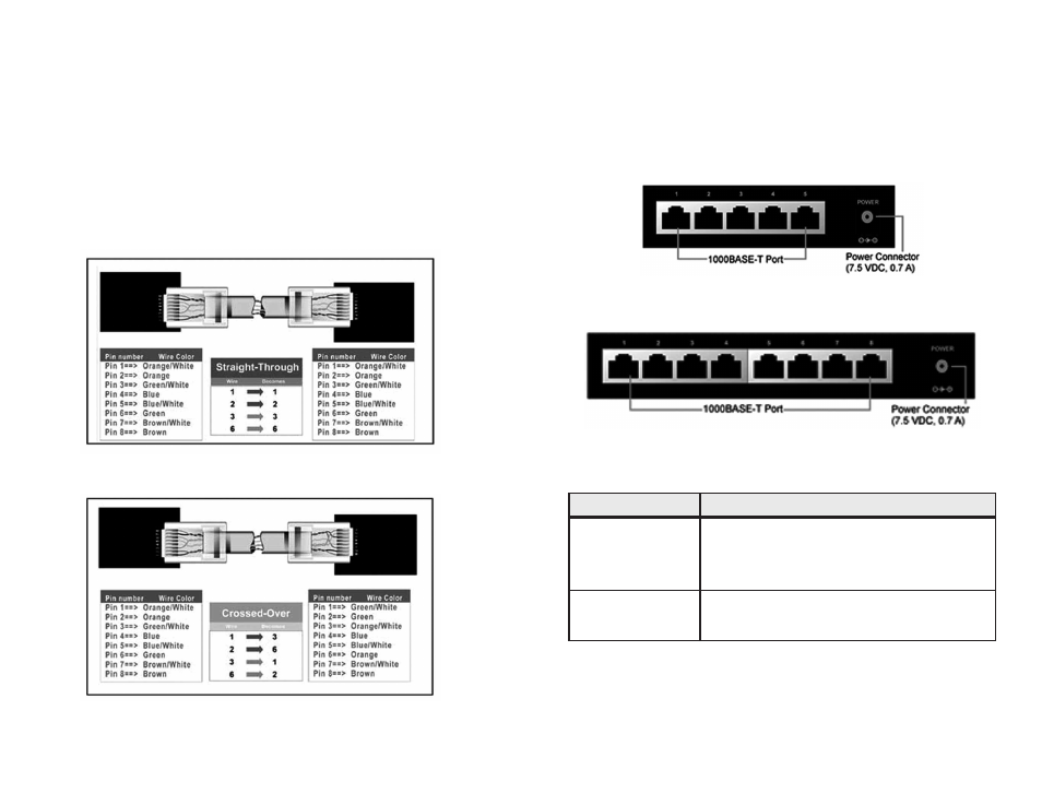
2.2 Rear View
Figure 2.1-1 illustrates the rear panel of the MicroGST-5 Switch;
Figure 2.1-2 illustrates the rear panel of the MicroGST-8 Switch.
Table 2.2-1 shows the por t function of both switches.
Figure 2.2-1
Figure 2.2-2
Table 2.2-1
wires of 1,2,3,6 are reversed so that wire 1 become 3 at the other end
of the cable, 2 becomes 6, and so for th.
To determine which wire is wire 1, hold the RJ-45 plug with the spring
clip facing towards the ground and the end pointing away from you. The
copper wires exposed upwards to your view. The first wire on the far left
is wire 1. You can also refer to the illustrations and char ts of the
internal wiring on the following page.
Figure 3-1 shows the diagram of Straight Through Cables. Figure 3-2
shows the diagram of Crossover Cables.
Figure 3-1: Straight Through Cabling
Figure 3-2: Crossover Cabling
6
3
Port
Function
1000Base-T Ports
5-Port: Por ts 1–5
These 5/8 Gigabit por ts connect to network
8-Port: Por ts 1–8
devices such as PCs, print ser vers and other
network peripherals at 1000 Mbps.
Power Connector
This is where you will connect the AC
power adapter.