4 technical specifications, Warranty statement, Installation – UNICOM Electric MICROGST-8 User Manual
Page 4: 1 front view and leds
2
7
4 Technical Specifications
■
MicroGST-5 (5-Port 10/100/1000T switch)
Ports
5-Por t 1000Base-T
Buffer Memory
104 KB
MAC Address
1000
Jumbo Frame
9 KB
Size (W x D x H)
Metal case: 109 x 84 x 27 (mm)
Plastic case: 120 x 84 x 32 (mm)
Weight
Metal case: 0.48 kg
Plastic case: 0.49 kg
Power
7.5 VDC, 0.7 A
EMI/EMC
FCC Class A, CE
■
MicroGST-8 (8-Port 10/100/1000T switch)
Ports
8-Por t 1000Base-T
Buffer Memory
192 KB
MAC Address
4000
Jumbo Frame
9 KB
Size (W x D x H)
Metal case: 158 x 104 x 27 (mm)
Plastic case: 170 x 106 x 32 (mm)
Weight
Metal case: 0.63 g
Plastic case: 0.49 kg
Power
7.5 VDC, 0.7
EMI/EMC
FCC Class A, CE
MicroGST-5 and MicroGST-8 Switches:
Operating Temperature
0°C to 40°C (32°F to 122°F)
Storage Temperature
-40°C to 70°C (-40°F to 158°F)
Operating Humidity
20% to 85% relative humidity, non-condensing
Storage Humidity
20% to 90% relative humidity, non-condensing
5. Warranty statement
We provide this limited warranty for it originally purchased the product from us or its authorized reseller
or distributor. We guarantee that equipment is free from physical defects in workmanship and material
under normal use from the date of original retail purchase of the Hardware. If the product proves
defective during this warranty period, call our Customer Ser vice in order to obtain a Return
Authorization number. Be sure to have a proof of purchase on hand when calling. Return requests
cannot be processed without proof of purchase. When returning a product, mark the Return
Authorization Number clearly on the package pack and include you original proof of purchase. All
customers outside the R.O.C. shall be held responsible for shipping and handling charges. In no event
shall our liability exceed the price paid for the product from direct, incidental or consequential damage
resulting from the use of the product, its accompanying software, or its documentation. We make no
warranty or representation, expressed, implied, or statutor y, with respect to its products or the contents
or use of this documentation and all accompanying software, and specifically disclaim its quality,
per formance, merchantability, or fitness for any par ticular purpose. We reser ve the right to revise or
update its products, software, or documentation without obligation to notify any individual or entity.
2. Installation
This chapter describes the function of the switch components and
shows how to install it on your network. Basic knowledge of networking
is assumed. Read this chapter completely before installation.
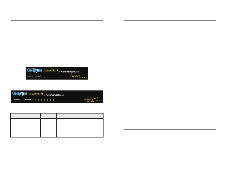
2.1 Front View and LEDs
Figure 2.1-1 illustrates the front panel of the MicroGST-5 Switch;
Figure 2.1-2 illustrates the front panel of the MicroGST-8 Switch.
Table 2.1-1 describes the LED display of both switches.
Figure 2.1-1
Figure 2.1-2
Table 2.1-1
LED
Status
Color
Description
Power
On
Green
The switch is supplied with
suitable power.
LNK/ACT
Blinks
Green
The por t is receiving or
transmitting data.