Flow diagrams, Hydraulic flow diagrams – Toro GREENSMASTER 3100 User Manual
Page 23
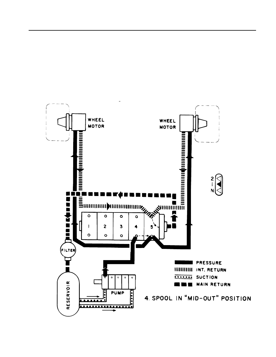
Hydraulic Flow Diagrams
Traction, No. 1 Position
When engine is started, pump draws oil from reservoir
through two suction lines. Oil from one section of pump
passes through fitting in No. 4 spool valve into valve.
Traction lever, when located in No. 1, positions spool so
oil is directed to flow into the No. 5 metering valve
section. When the traction pedal is pushed forward oil
flows out lines at rear of metering valve section to each
motor to drive the motors. Low pressure oil returns to
valve through valve and main return line, through filter
to reservoir.
Greensmaster
®
3100
Page 4 - 5
Hydraulic Flow Diagrams