Tractor creeping, Transmission drive belt – Troy-Bilt RZT SERIES ZT42 User Manual
Page 31
31
s
ectiOn
7 — s
ervice
Using the ratchet for leverage, pivot the idler bracket and
3.
idler pulley away from the backside of the ‘V” belt; then lift
the belt off and above the engine pulley and off the idler
pulley.
With the belt loose, lift the belt off, up and over the two
4.
transmission drive pulleys. Remove the belt from the
engine and idler pulleys.
Loop the new belt and slide over and onto the two
5.
transmission pulleys.
Route the belt above the idler bracket back to the engine
6.
drive pulley. Lift the belt over the PTO pulley and above the
engine drive pulley.
Using the ratchet for leverage, pivot the idler bracket and
7.
idler pulley against the spring tension; then slip the belt
down into the engine drive pulley and onto the idler pulley.
Release the idler bracket so that the idler pulley tightens
8.
against the back side of the belt and tensions the drive belt.
Reinstall the deck drive belt.
9.
Tractor Creeping
Creeping is the slight forward or backward movement of the
tractor when the engine is running at high idle and the drive
control levers are opened out in the neutral position.
If after operating the tractor for some time, it begins to creep
while in the neutral position, adjust the transmission control rods
as follows.
Place the front of the tractor against an immovable object
1.
(e.g. wall, post, etc.).
Jack up the rear of the tractor so that both rear wheels are
2.
approximately one inch of the ground.
With the engine running at high idle and the drive control
3.
levers opened out in the neutral position, and the parking
brake disengaged, check the rear wheels for rotation.
If only one wheel is rotating, locate the transmission
4.
control rod beneath the frame at the front of the rear tire. If
both wheels rotate, locate both control rods. See Fig. 7-9.
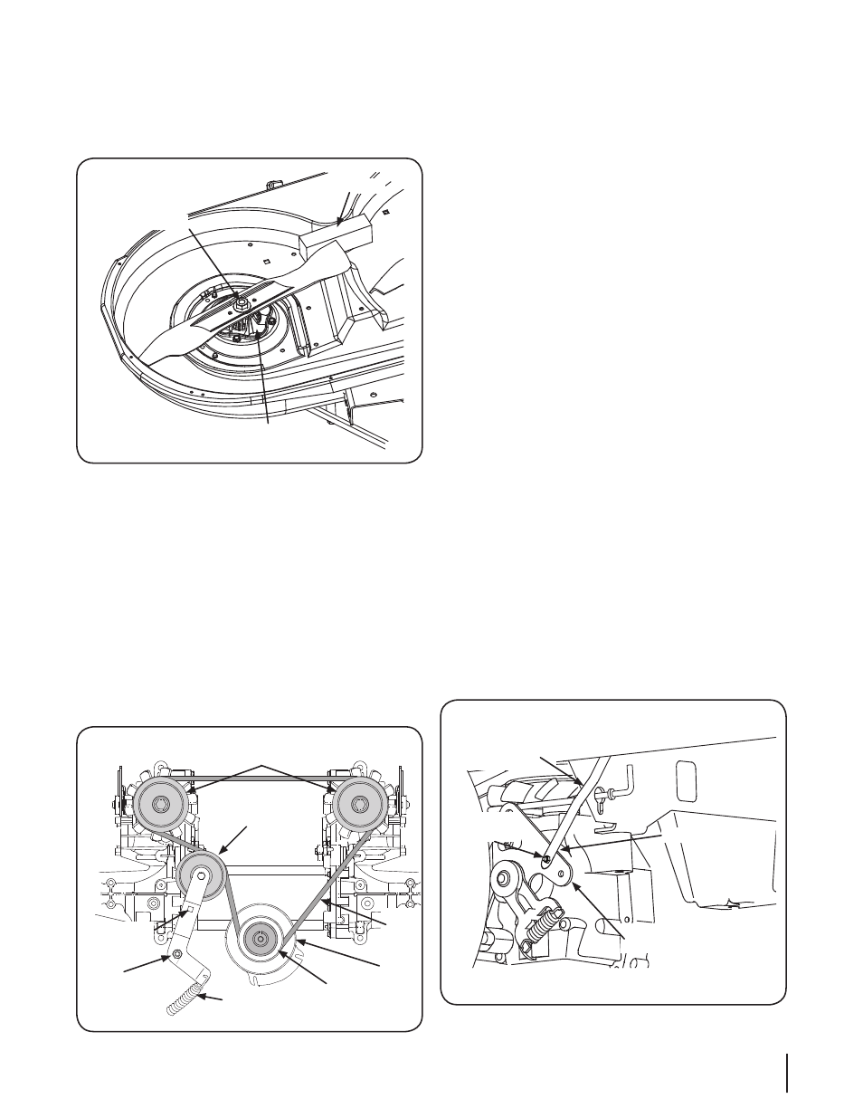
Use a
2.
15⁄16” wrench to hold the hex nut on top of the spindle
assembly when loosening the hex nut securing the blade.
A block of wood may be placed between the deck housing
and the cutting edge of the blade to help in breaking loose
the hex nut securing the blade. See Fig. 7-7.
When reinstalling the blades, be sure they are installed so that
3.
the wind wings are pointing upward toward the top of deck.
Tighten the blade nuts to 70-90 ft. lbs.
4.
Reinstall the deck (refer to Deck Installation on page 31).
5.
Transmission Drive Belt
If the transmission drive belt becomes worn and causes the drive
transmissions to slip, the drive belt must be replaced. To replace
the drive belt, proceed as follows:
Remove the deck drive belt from the PTO clutch on the bottom
1.
of the engine following the instructions in Deck Removal.
From beneath the rear of the tractor, insert a
2.
3⁄8” drive ratchet
into the square hole of the drive idler bracket. See Fig. 7-8.
Transmission
Drive Pulley
Square Hole
Idler
Bracket
Idler Bracket
Spring
Engine
Pulley
PTO
Pulley
Drive
Belt
Idler
Pulley
Figure 7-8
RH Transmission
Control Rod
Hex Screw
Transmission
Control Arm
Flange
Lock Nut
Figure 7-9
Hex Flange Nut
Spindle Assembly
Wood Block
Figure 7-7