Assembly, Mower mounting, Lift control feedlines – Tiger Products Co., Ltd JD 5065 / 5085 - 5105M User Manual
Page 49
ASSEMBLY
Assembly Section 2-19
MOWER MOUNTING
Check that all grease zerks have been installed in the draft beams pivot arm, left linkage arm,
right linkage arm, and cylinder mounting ears.
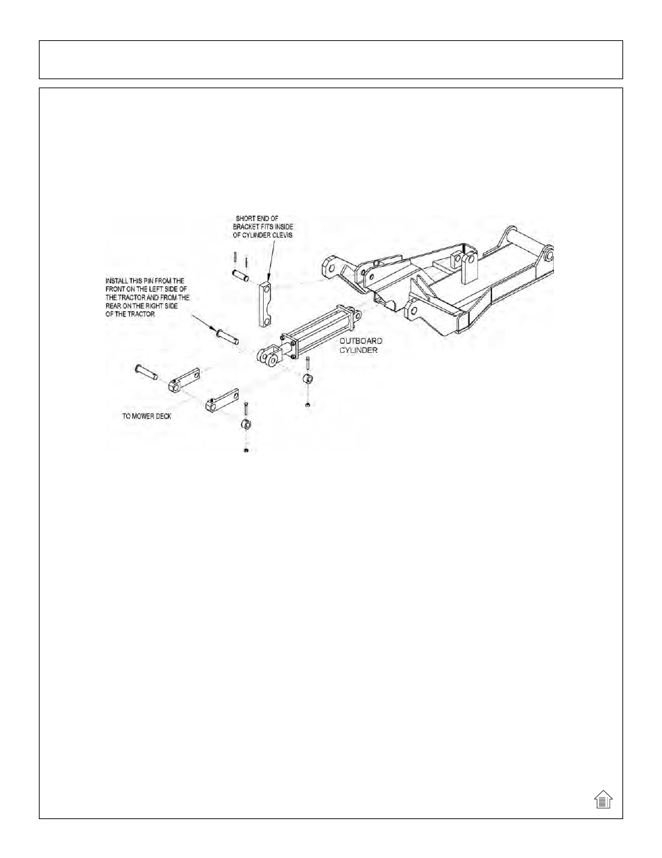
Using a clevis pin and roll pins, connect the pivot arm to clevis on draft beam. NOTE: Make
sure the longer distance between the cutout and the end of the pivot arm is closest to the draft
beam pivot ears on the center tube as shown in the diagram below. Also make sure the cutout
on the pivot arm faces into tube of draft beam.
(ASM-C-0077)
Slide other end of pivot arm with short distance between the cut-out and the end of the pivot
arm, into the cylinder clevis. Next, line up the holes of the left and right lift linkage arms outside
of the cylinder clevis holes. Connect with linkage pin, shims (as required), boss, cap-screw,
lock-washer and hex nut as shown.
To connect the bonnet to the draft beam, slide the extension arms of the draft beam between
the mounting ears on the inner end of the bonnet. Line up the holes and secure with swivel pin,
cap-screw, lock-washer, and hex nut (both sides). See parts book illustration.
Next, slide the left and right linkage arms up to the slotted ear on the side of the deck.
Secure with linkage pin, shims, boss, cap-screw, lock-washer and hex nut. See illustration in
Parts Section.
LIFT CONTROL FEEDLINES
Hose lengths will vary between tractor applications such as cab and non-cab units. See the
Parts Section that pertains to your tractor for hose applications.
Install a hose from the bottom or inner valve port (behind cab for cab units, on stand for non-
cab units) to the restrictor on the inboard cylinder gland.
Install a hose from the upper or outer valve port to the restrictor on the outboard cylinder butt.
See Parts Section for part numbers and hose routing illustrations.
(ASM-C-0093)