For hvac installer only, Intended application for ultra-aire 135h, Registrations – Therma-Stor Products Group UA-135H User Manual
Page 4: Specifications, Installation, Important
1. Intended Application for Ultra-Aire 135H
For the ideal installation, draw air from the central part of the home
and return it to the isolated areas of the home like the bedrooms,
den, utility room, or family room. The ductwork of the existing
heating system can be used to supply air to the home.
2. Registrations
The Ultra-Aire 135H (P/N 4025080) conforms to UL STD 1995.
Certified to CAN/CSA STD C22.2 No. 236.
3. Specifications
Model:
UA-135H Air Purifying Dehumidifier
Electrical:
110-120 VAC, 12 Amps, 60 Hz, grounded
Capacity:
135 pints/day @ 80°F, 60% RH
Operating Temp.:
56°F min., 100°F max.
Air Flow:
355 CFM without external ducting
335 CFM @ .20 IWG external static
315 CFM @ .40 IWG external static
Refrigerant Charge:
1 lb., 12 oz. R22
Duct Connections:
Round 10" inlet, 10" outlet
Filter Size:
Pleated cloth: 2" x 20" x 24"
High Efficiency: 4" x 20" x 24" (optional)
Unit Size
(w/o duct collars):
31"L x 21"W x 18
3
/
4
"H
Shipping Size:
37"L x 25"W x 28
1
/
2
"H
Unit Weight:
99.3 lbs.
Shipping Weight:
138 lbs.
4. Installation
4.1 Installation Checklist
IMPORTANT:
Prior to installation of the UA-135H, the
following checklist should be reviewed. The UA-135H can be
installed in a variety of locations to meet the owner's needs and
integrate with existing forced air systems or existing ductwork
if desired. The location choice is contingent on a variety of
requirements not limited to: ease of service, controls access,
drainage, filtration, power, fresh-air ventilation, water damage
prevention, and current regulatory codes (ASHRAE, fire, etc). Please
address all of these issues before you select the devices location.
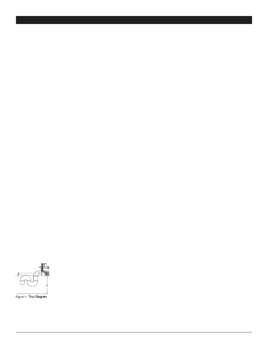
4.1A Drainage and Trap
Unit should be located in an area where the
UA-135H's condensate (water) may be easily
routed to a suitable drain. Space and location
requirements should take into account the
incorporation of a trap for the assembly as
shown in section 4.4.
4.1B Filter Box & Fresh Air Ventilation
Unit location should be in an area where the unit’s return
(intake) side will be easily accessible for ducting. Ducting the
optional fresh air ventilation to the filter box should be easily
accomplished by the unit's location.
4.1C Power Accessibility
Unit should be located in an area where the cord's length (6') should
easily reach a 115 VAC electrical outlet with a minimum of a 15 A
circuit capacity.
4.1D Space
Location should have enough clearance to handle the unit's overall
dimensions as well as the necessary return/supply ductwork to the
unit and the additional 4" in height for the unit to drain properly.
The filter box should be accorded enough space to allow for the
opening of the filter access panel and for the replacement of the
filter elements.
4.1E Low Voltage Wiring
Unit Location should be in an area where field wiring the remote
controls (low voltage) to the unit will be possible.
4.1F Sound
The UA-135H produces sound levels from 50 to 60 dB. If necessary,
do not locate unit in or adjacent to areas which the unit's sound
might be aggravating to the end user. For additional noise control,
attach 3⁄4" plywood surround.
4.1G Back-Draft Damper
It is recommended that a back draft damper be utilized on the supply
ducts for the UA-135H. The unit location should be able to permit
this accessory to be installed if requested by the end user. For more
information please call customer service at (800) 533-7533.
4.1H Support Structure and Suspension
Place the UA-135H on supports to raise the base of the unit
approximately 4" above the horizontal floor below it. Raising the
UA-135H will help the unit drain with gravity flow. Do not place the
UA-135H directly on structural building members without vibration
absorbers or unwanted noise may result.
The UA-135H may be suspended with steel hanger straps (plumbers
tape) or a suitable alternative from structural members, as long as
the suspending assembly supports the 5 individual feet of the UA-
135H's base in its entirety. Remember to place a drain pan under the
unit if it is suspended above a finished area or above an area where
water leakage could cause damage.
4.2 External Insulation Kit
An external insulation kit is available for the UA-135H. This will
help prevent the cabinet from sweating if the unit is installed in an
unconditioned space. This kit will increase the efficiency of the unit
by eliminating unwanted heat transfer between the unit and the
space. See the optional accessories list for information on the kit.
FOR HVAC INSTALLER ONLY
4
Ultra-Aire 135H Installer’s & Owner’s Manual