Troubleshooting, Ethernet cable specifications, Installing slide-in-module(s) – Transition Networks C/E-100BTX-FRL-03 User Manual
Page 2
1. Is the power LED on the media converter illuminated?
NO
•
Is the Slide-In-Module properly connected to the Media Conversion Center
chasis backplane?
•
Is the Power Supply Module properly connected both to the Media Conversion
Center chasis backplane and to the AC outlet?
•
Contact Technical Support at (800) 260-1312/ (800) LAN-WANS.
YES
•
Proceed to step 2.
2. Is the 100BASE-TX Link LED illuminated?
NO
•
Check UTP cables for proper connection and pin assignment. (See above.)
•
Contact Technical Support at (800) 260-1312/ (800) LAN-WANS.
YES
•
Proceed to step 3.
3. Is the fiber Link LED illuminated?
NO
•
Check fiber cables for proper connection.
•
Verify that TX and RX cables on media converter are connected to RX and TX
ports, respectively, on the other 100BASE-FX device.
•
Refer to Tech Tips available at: http://www.transition.com
•
Contact Technical Support at (800) 260-1312/ (800) LAN-WANS.
YES
•
Contact Technical Support at (800) 260-1312/ (800) LAN-WANS.
Troubleshooting
The physical characteristics of the media cable must meet or exceed IEEE
802.3u 100BASE-TX and 100BASE-FX specifications.
ETHERNET CABLE SPECIFICATIONS
100BASE-FX CABLE SPECIFICATIONS
SINGLEMODE
Fiber-optic Cable Recommended:
9 µm singlemode fiber
Fiber-optic Transmitter Power:
min: -15.0
dBm
max: -8.0
dBm
Fiber-optic Receiver Sensitivity:
min: -32.5
dBm
max: -8.0
dBm
Wavelength:
1300nM
Bit error rate:
≤
10
-9
Maximum Cable Distance:
20 kilometers
MULTIMODE
Fiber-optic Cable Recommended:
62.5 / 125 µm multimode fiber
Optional:
100 / 140 µm multimode fiber
85 / 125 µm multimode fiber
50 / 125 µm multimode fiber
Fiber-optic Transmitter Power:
min: -19.0
dBm
max: -14.0
dBm
Fiber-optic Receiver Sensitivity:
min: -32.5
dBm
max: -14.0
dBm
Wavelength:
1300nM
Bit error rate:
≤
10
-9
Maximum Cable Distance:
2 kilometers
100BASE-TX CABLE SPECIFICATIONS
Category 5 wire or better is required. Either shielded twisted pair
(STP) or unshielded twisted pair (UTP) can be used. Use a straight-
through cable configuration (see back page).
CATEGORY 5:
Gauge
24 to 22 AWG
Attenuation
20 dB/1000’ @ 10 MHz
Impedance 100
Ω
±10% @ 10 MHz
Maximum Cable Distance:
100 meters (330 feet)
Installing Slide-In-Module(s)
CAUTION: Wear a grounding device and observe electrostatic discharge precautions when
installing Media Converter Slide-in-Module(s) in the 16-Slot Media Conversion Center.
Failure to observe this caution could result in damage to, and subsequent failure of, the
Media Converter Slide-in-Module(s).
NOTE: Media Converter Slide-in-Modules can be installed in any installation slot, in any
order.
To install the Media Converter Slide-in-Module in the E-MCC-1600 chassis:
1. Remove Media Converter Slide-in-Module protective plate from selected installation slot
by removing two screws that secure plate to front of E-MCC-1600. Retain one installation
screw.
2. Carefully slide Media Converter Slide-in-Module into installation slot, aligning Media
Converter Slide-in-Module with installation guides. NOTE: Ensure that the Media
Converter Slide-in-Module is firmly seated against the backplane.
3. Secure Slide-in-Module by installing retained installation screw.
100BASE-FX CABLE CONNECTIONS
•
Be certain that the correct mode and wavelength fiber cable is used for single-
mode and/or for multimode fiber cable installations.
100BASE-TX CABLE CONNECTIONS
•
Be certain that the MDI/MDI-X switch located ON the Slide-In-Module circuit
board is set correctly before installing Slide-In-Module in Media Conversion
Center. Cable connections between a hub and the media converter require the
MDI/MDI-X switch to be set to MDI. Cable connections between the media
converter and a terminal, transceiver or NIC require the switch to be set to MDI-
X.
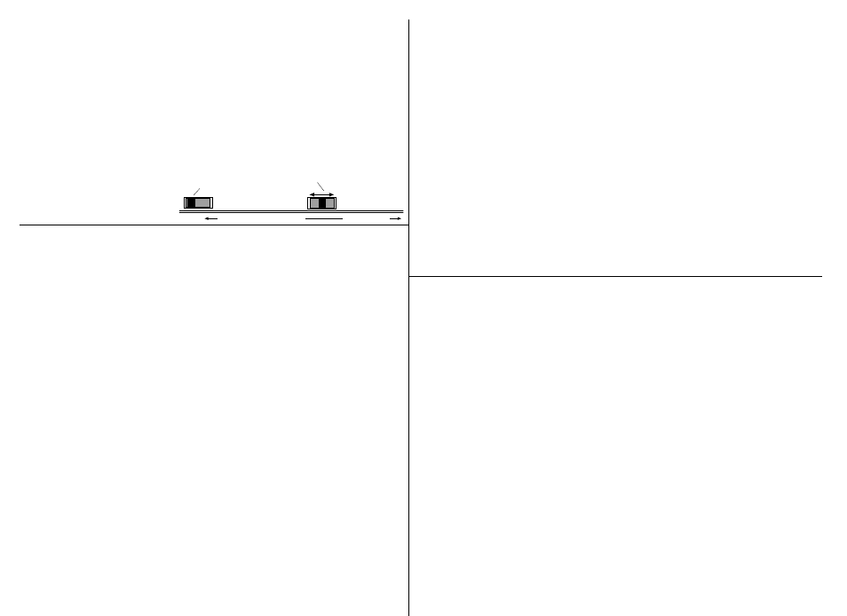
•
Using small flatblade
screwdriver or similar tool,
set MDI/MDI-X switch
position for site installation.
MDI
position
MDI-X
position
toward network connectors
toward chassis
Leave in default position
Set switch
C/E-100BTX-FRL-03