True food international equipment, inc, Ar2-28 instructions for use, Description indications installation – True Manufacturing Company TGU-2 User Manual
Page 22: Operation, Wiring diagrams technical data, Display, Info menu, Stand-by, Keypad lock, Selection of second parameter group
............ www.truemfg.com ............
True Food International Equipment, Inc.
20
20
Thank you for having chosen an LAE electronic product. Before installing the instrument, please read this instruction booklet carefully in order to ensure safe
installation and optimum performance.
AR2-28 INSTRUCTIONS FOR USE
Fig.1 - Front panel
DESCRIPTION
INDICATIONS
INSTALLATION
The AR2-28 controller, size 107x95x47 mm (WxHxD), is to be secured to a DIN rail in such a position as to ensure that no liquid infiltrates causing serious
■
damage and compromising safety.
Make sure that electrical connections comply with the paragraph “wiring diagrams”. To reduce the effects of electromagnetic disturbance, keep the sensor
■
and signal cables well separate from the power wires.
Place the probe T1 inside the room in a point that truly represents the temperature of the stored product.
■
Place the probe T2 on the evaporator where there is the maximum formation of frost.
■
The function of probe T3 is determined by the parameter T3. With
■
T3=DSP the probe measures the temperature to be displayed. With T3=CND the probe
measures the condenser temperature, it must therefore be placed between the fins of the condensing unit. With
T3=2EU the probe measures the temperature
of the second evaporator and it must therefore be placed where there is the maximum formation of frost. With
T3=NON, the third probe is disabled.
OPERATION
DISPLAY
During normal operation, the display shows either the temperature measured or one of the following indications:
Defrost in progress
Condenser high pressure alarm
Controller in stand-by
Room high temperature alarm
Condenser clean warning
Room low temperature alarm
Door open alarm
Probe T1 failure
Condenser high temperature alarm
Probe T2 failure
Probe T3 failure
INFO MENU
The information available in this menu is:
Instant probe 1 temperature
End time for timed actions
*
Instant probe 2 temperature
Maximum probe 1 temperature recorded
*
Instant probe 3 temperature
Minimum probe 1 temperature recorded
Minutes of the Real Time Clock
** Compressor working weeks
Hours of the Real Time Clock
Keypad state lock
Start time for timed actions
*: displayed only if enabled (see §Configuration Parameters) **: displayed only if
ACC > 0
Access to menu and information displayed.
Press and immediately release button
■
.
With button
■
or select the data to be displayed.
Press button
■
to display value.
To exit from the menu, press button
■
or wait for 10 seconds.
Reset of THI, TLO, CND recordings.
With button
■
or select the data to be reset.
Display the value with button
■
.
While keeping button
■
pressed, use button
.
SETPOINT : display and modification
Press button
■
for at least half second, to display the setpoint value.
By keeping button
■
pressed, use button or to set the desired value
(adjustment is within the minimum
SPL and the maximum SPH limit).
When button
■
is released, the new value is stored.
STAND-BY
Button , when pressed for 3 seconds, allows the controller to be put on a standby or output control to be resumed (with
SB=YES only).
KEYPAD LOCK
The keypad lock avoids undesired, potentially dangerous operations, which might be attempted when the controller is operating in a public place. In the INFO
menu, set parameter
LOC=YES to inhibit all functions of the buttons. To resume normal operation of keypad, adjust setting so that LOC=NO.
SELECTION OF SECOND PARAMETER GROUP
It’s possible to select control parameters between two different pre-programmed groups, in order for the fundamental control parameters to be adapted quickly
to changing needs. Changeover from Group
I to Group II (and vice versa) may take place MANUALLY by pressing button for 2 seconds (with IISM=MAN),
or AUTOMATICALLY when heavy duty conditions are detected (with
IISM=HDD), or when IISM=DI2 and the AUXILIARY INPUT DI2 is activated (the activation
of DI2 selects Group
II), or finally at the time specified by STT and EDT parameters (with IISM=RTC). If IISM=NON, switchover to Group II is inhibited. The
activation of Group
II is signalled by the lighting up of the relevant LED on the controller display.
REAL TIME CLOCK SETTING
The Real Time Clock (RTC) can be adjusted directly from the Info Menu (see Setpoint modification procedure). Tens of minutes MIN range from 0 to 59 and
Hours HRS range from 0 to 23. If RTC is adjusted just before an upcoming change of hour, verify the correctness of the setting again. The RTC does not
automatically change upon Daylight Saving Time.
DEFROST
Automatic defrost. Defrost starts automatically at fixed time-intervals or at programmed scheduled (up to six per 24 hours).
Timed defrost
■
. With
DFM=TIM defrosts take place at regular intervals when the timer reaches the value of DFT. For example, with DFM=TIM and DFT=06,
a defrost will take place every 6 hours.
Scheduled defrost
■
. With
DFM=RTC defrost takes place at time specified by DH1...DH6. The format of time is “HH.M”, where HH are hours and M are tens
STT
HH.M
Start time for timed actions.
Time at which the second parameter group or the light output is switched. Accepted values go from 00.0 to 23.5. Example:
STT=8.3 and IISM=RTC means that at 8.30 AM the second group will be activated.
EDT
HH.M
End time for timed actions. See STT.
LSM
NON;
MAN;
RT0;
RT1;
DOR
Light control mode
NON : light output not controlled.
MAN : light ouput controlled through button (if OAx=LGT).
RT0 : light output switched on at EDT time, off at STT time.
RT1 : light output switched on at STT time, off at EDT time.
DOR : light ouput switched on when door is opened (if OAx=LGT).
OA1
NON;
0-1;
LGT;
2CU;
2EU;
AL0;
AL1
AUX 1 output operation
NON : output disabled (always off).
0-1 : the relay contacts follow the on/standby state of controller.
LGT : output enabled for light control.
2CU : output programmed for the control of an auxiliary compressor.
2EU : output enabled for the control of the electrical defrost of a second evaporator.
AL0 : contacts open when an alarm condition occurs.
AL1 : contacts make when an alarm condition occurs.
OA2
See OA1
AUX2 output operation. See OA1.
2CD
0...120 sec Auxiliary compressor start delay. If OAx=2CU the auxiliary output is switched on with a delay of 2CD seconds after the main
compressor has cut-in. Both compressors are turned off at the same time.
INP
SN4; ST1
Temperature sensor selection. With INP=SN4, the probes must be the LAE models SN4..; with INP = ST1, the probes must
be the LAE models ST1...
OS1 -12.5..12.5°C Probe T1 offset.
T2
NO/YES
Probe T2 enabling (evaporator).
OS2 -12.5..12.5°C Probe T2 offset.
T3
NON;
DSP;
CND;
2EU
Auxiliary probe T3 operation
NON : probe T3 not fitted.
DSP : temperature T3 to be displayed.
CND : condenser temperature measurement.
2EU : second evaporator temperature measurement.
OS3 -12.5..12.5°C Probe 3 offset.
TLD
1...30 min
Delay for minimum temperature (TLO) and maximum temperature (THI) logging.
SIM
0...100
Display slowdown.
ADR
1...255
AR2-28 address for PC communication.
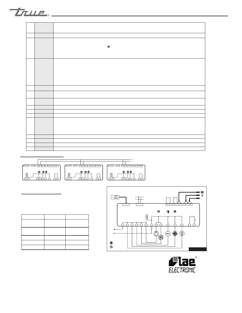
WIRING DIAGRAMS
TECHNICAL DATA
Power supply
AR2-28.…D 12Vac/dc ±10%, 3W
AR2-28....E 230Vac±10%, 50/60Hz, 3W
AR2-28....U 115Vac±10%, 50/60Hz, 3W
Relay output max loads (240Vac)
AR2-28..S/T..-. AR2-28..Q/R..-.
Compressor
16A resistive
8 FLA 48 RLA
12A resistive
8 FLA 48 RLA
Evap. Fan
8A resistive
2 FLA 12 RLA
8A resistive
2 FLA 12 RLA
Defrost
16A resistive
12A resistive
Auxiliary loads 1 7A resistive
7A resistive
Auxiliary loads 2 7A resistive
7A resistive
Input
NTC 10KΩ@25°C LAE Part No. SN4...
PTC 1000Ω@25°C LAE Part No. ST1…
Measurement Range
-50…120°C, -55…240°F
-50 / -9.9 … 19.9 / 80°C (NTC10K only)
Measurement accuracy
<0.5°C within the measurement range
Real Time Clock battery
>150 hours; self-rechargeable
VIA PADOVA, 25
31046 ODERZO /TV /ITALY
TEL. +39 - 0422 815320
FAX +39 - 0422 814073
www.lae-electronic.com
E-mail: [email protected]
Thermostat output
Fan output
Alarm
Defrost output
Activation of 2nd parameter set
Manual activation / Increase button.
Exit / Stand-by button.
Info / Setpoint button.
Manual defrost / Decrease button.
Operating conditions
-10 … +50°C; 15%...80% r.H.
CE - UL (Approvals and Reference norms)
EN60730-1; EN60730-2-9; EN55022 (Class B);
EN50082-1
SA32385, UL 60730-1A
AR2-28C1S5E-B
DI2
Maximum total current 17.5A
Power
Supply
L
N
data I/O
RS485
PC comm.
LCD-5S
or
RU33
16(4)A
16(8)A
A
B
8(2)A
7A
Evaporator fan
Condenser fan
T3
T2
T1
remote
Door
7A
AUX 2
AUX 1
Aux
14
15
16
17
18
19
9
10
11
7
8
6
1
2
26
29
31
32
33
28
30
27
FUSE
-
-
-
+
+
+
31
29
30
27
28
9
14
33
32
DI2
26
T3
8
6
7
10
AR2-28C1S5E-B
11
1
2
AUX2
AUX1
T2
T1
Door
data
remote
31
29
30
27
28
9
14
33
32
DI2
26
T3
8
6
7
10
AR2-28C1S5E-B
11
1
2
AUX2
AUX1
T2
T1
Door
data
remote
31
29
30
27
28
9
14
32
33
DI2
26
T3
8
6
7
10
AR2-28C1S5E-B
11
1
2
AUX2
AUX1
T2
T1
Door
data
remote
Fig.3 Connection for synchronising defrost start and termination