Specifications, Warranty & warranty registration, Technical specification – Tripp Lite RELAYIOCARD User Manual
Page 4: Application example, Internal circuit, Programmable contacts, Power option in win 2000/xp
4
3. Specifications
Technical Specifications
Size
130 x 60 mm
Weight
200g
Operating Temperature
0 ~ 40° C
Operating Humidity
10 ~ 80%
Power Input
8~20V DC
Power Consumption
1.2 Watts
Output Contact Rating
Maximum
DC Voltage
DC Current
Input
24V
1A
Input Rating
Maximum
DC Voltage
DC Current
Input
24V
10mA
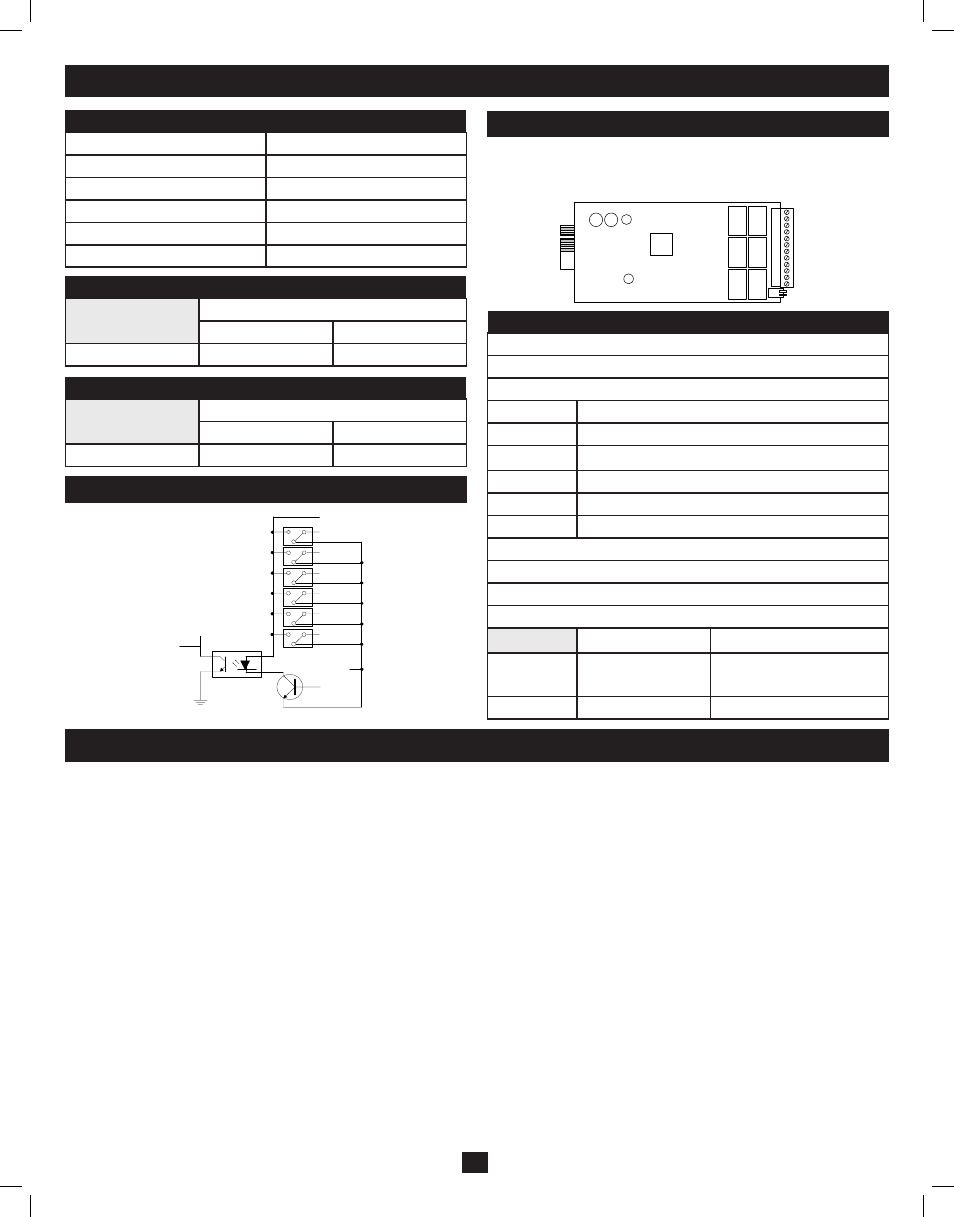
Internal Circuit
Outline
I/O Pinout
GND-R: Ground for relays
Common: 12~24V DC
Default Alarm Event
R1
Summary Alarm
R2
Power Fail
R3
Battery Low
R4
On Bypass
R5
Overload
R6
Over Temperature
Input: Remote shutdown or battery test
Tx: Transmit to PC, connect to DB9-pin2
Rx: Receive from PC, connect to DB9-pin3
GND-C: Ground for configuration Tx and Rx pins
OFF (default)
ON
SW1
Normal open for
default settings
Normal close for
default settings
SW2
Default settings
Customized settings
PROGRAMMABLE RELAY I/O CARD
USER MANUAL
PRESENTATION
FEATURES
This relay I/O card is an UPS management
product with 6 relay output contacts for monitoring
the status and 1 input contact as a shutdown UPS
or a battery test command.
Features:
z
Monitor UPS events.
z
6 programmable relay output contacts.
z
Configurable normal open or normal close for
each relay contact.
z
Configurable UPS shutdown delay time.
z
Configurable input signal as shutdown UPS or
battery test.
z
Has the ability to protect up to 6 computers
unattended shutdown gracefully.
TECHNICAL SPECIFICATION
TECHNICAL SPECIFICATION
Size
130 x 60 mm
Weight
200 g
Operating Temperature 0 ~ 40q C
Operating Humidity
10 ~ 80 %
Power Input
8 ~ 20V DC
Power Consumption
1.2 Watts
OUTPUT CONTACT RATING
Maximum
DC Voltage DC Current
Relay
R1~R6
24 V
1A
INPUT RATING
Maximum
DC Voltage DC Current
Input
24 V
10 mA
APPLICATION EXAMPLE
In this case we’ll use the default settings, please
set SW1 and SW2 to the OFF position. Apply
12VDC to
Common contact and connect the
lamps to
R1~R6 terminals. Install a push button
from the Common contact to the input terminal.
Press the button for at least 3 seconds to
shutdown the UPS remotely.
Common
GND-R
R1
R2
R3
R4
R5
Input
+12V
Summary Alarm
Power Fail
Battery Low
On Bypass
Overload
Shutdown UPS
R6
Over Temperature
INTERNAL CIRCUIT
R1
R2
R3
R4
R5
Common
GND-R
Input
+5V
CPU Pin
R6
OUTLINE
GND-R
Common
R1
R2
R3
R4
R5
R6
Input
Tx
Rx
GND-C
SW1
SW2
I/O PINOUT
GND-R: Ground for relays
Common: 12~24VDC
Default Alarm Event
R1
Summary Alarm
R2
Power Fail
R3
Battery Low
R4
On Bypass
R5
Overload
R6
Over Temperature
Input: Remote shutdown or battery test
Tx: Transmit to PC, connect to sub9-pin2
Rx: Receive from PC, connect to sub9-pin3
GND-C: Ground for configuration Tx and Rx pins
OFF (Default)
ON
SW1 Normal open
for default settings
Normal close
for default settings
SW2 Default settings
Customized settings
PROGRAMMABLE CONTACTS
COMMUNICATION SETUP
1. Connect
Tx to pin2, Rx to pin3 and GND-C to
pin5 of PC RS232 port.
2. In the Windows environment, launch the
Hyper- Terminal program then open the
specified COM port.
3. Set the following properties:
Baud rate:
2400, Data Bits: 8, Parity: None
Stop Bit:
1, Flow Control: None
CONFIGURATION
1. Press
programmable relay card.
_8365HOD\&DUG_
)LUPZDUH9HUVLRQ5HOD\&DUG9
>@&XVWRPL]H2XWSXW5HOD\
>@&RQILJXUH,QSXW6LJQDO
>@&XVWRPL]H1RUPDO2SHQRU1RUPDO&ORVH
>@4XLW
3OHDVH(QWHU 2. Press ‘1’ to configure the alarm event for R1~R6. Contacts R1~R6 can be configured for different power events. 3OHDVH(QWHU Once the configuration is complete SW2 MUST be switched to the ON position to apply the new settings, switch SW2 back to the OFF position to reset to the default settings. 3. Press ‘2’ to configure the Input signal. 3OHDVH(QWHU In this menu, the input signal can be redefined as shutdown UPS or battery test signal. Meanwhile, the UPS shutdown delay time is also adjustable to a maximum of 9999 seconds. 4. Press ‘3’ to configure the normal open or normal close for each relay. 3OHDVH(QWHU Once the configuration is complete SW2 MUST be switched to the ON position to apply the new settings. Switch SW2 back to the OFF position to reset to the default settings. 5. Press ‘0’ to quit this configuration session. The system would prompt you to save or not. Press ‘Y’ to save your settings, ‘N’ to ignore. POWER OPTION IN WIN 2000/XP This relay card has the ability to provide UPS signals for Windows NT4/2000/XP/2003. First connect the RS232 port on the PC to the relay card as shown: Then open the power option from control panel and click on the UPS tab to setup the signals polarity, select Positive for Power Fail, Low Battery and UPS Shutdown. Since the R1~R6 contacts are programmable, the output contacts can be configured for 3 computers with 2 signals (power fail and low battery) or 6 computers with one signal (power fail or low battery). Note: All of the computers must have the same earth ground potential. Connect all of the computers input power to the same UPS. Common GND-R R1 R2 R3 R4 R5 Input Power Fail R6 Battery Low RTS pin7 GND pin5 CTS pin8 DCD pin1 DTR pin4 Shutdown UPS PROGRAMMABLE RELAY I/O CARD USER MANUAL PRESENTATION FEATURES This relay I/O card is an UPS management product with 6 relay output contacts for monitoring the status and 1 input contact as a shutdown UPS or a battery test command. Features: Monitor UPS events. z 6 programmable relay output contacts. z Configurable normal open or normal close for each relay contact. z Configurable UPS shutdown delay time. z Configurable input signal as shutdown UPS or battery test. z Has the ability to protect up to 6 computers unattended shutdown gracefully. TECHNICAL SPECIFICATION TECHNICAL SPECIFICATION Size 130 x 60 mm Weight 200 g Operating Temperature 0 ~ 40q C Operating Humidity 10 ~ 80 % Power Input 8 ~ 20V DC Power Consumption 1.2 Watts OUTPUT CONTACT RATING Maximum DC Voltage DC Current Relay R1~R6 24 V 1A INPUT RATING Maximum DC Voltage DC Current Input 24 V 10 mA APPLICATION EXAMPLE In this case we’ll use the default settings, please set SW1 and SW2 to the OFF position. Apply 12VDC to Common contact and connect the lamps to R1~R6 terminals. Install a push button from the Common contact to the input terminal. Press the button for at least 3 seconds to shutdown the UPS remotely. Common GND-R R1 R2 R3 R4 R5 Input +12V Summary Alarm Power Fail Battery Low On Bypass Overload Shutdown UPS R6 Over Temperature INTERNAL CIRCUIT R1 R2 R3 R4 R5 Common GND-R Input +5V CPU Pin R6 OUTLINE GND-R Common R1 R2 R3 R4 R5 R6 Input Tx Rx GND-C SW1 SW2 I/O PINOUT GND-R: Ground for relays Common: 12~24VDC Default Alarm Event R1 Summary Alarm R2 Power Fail R3 Battery Low R4 On Bypass R5 Overload R6 Over Temperature Input: Remote shutdown or battery test Tx: Transmit to PC, connect to sub9-pin2 Rx: Receive from PC, connect to sub9-pin3 GND-C: Ground for configuration Tx and Rx pins OFF (Default) ON SW1 Normal open for default settings Normal close for default settings SW2 Default settings Customized settings PROGRAMMABLE CONTACTS COMMUNICATION SETUP 1. Connect Tx to pin2, Rx to pin3 and GND-C to pin5 of PC RS232 port. 2. In the Windows environment, launch the Hyper- Terminal program then open the specified COM port. 3. Set the following properties: Baud rate: 2400, Data Bits: 8, Parity: None Stop Bit: 1, Flow Control: None CONFIGURATION 1. Press programmable relay card. 3OHDVH(QWHU 2. Press ‘1’ to configure the alarm event for R1~R6. Contacts R1~R6 can be configured for different power events. 3OHDVH(QWHU Once the configuration is complete SW2 MUST be switched to the ON position to apply the new settings, switch SW2 back to the OFF position to reset to the default settings. 3. Press ‘2’ to configure the Input signal. 3OHDVH(QWHU In this menu, the input signal can be redefined as shutdown UPS or battery test signal. Meanwhile, the UPS shutdown delay time is also adjustable to a maximum of 9999 seconds. 4. Press ‘3’ to configure the normal open or normal close for each relay. 3OHDVH(QWHU Once the configuration is complete SW2 MUST be switched to the ON position to apply the new settings. Switch SW2 back to the OFF position to reset to the default settings. 5. Press ‘0’ to quit this configuration session. The system would prompt you to save or not. Press ‘Y’ to save your settings, ‘N’ to ignore. POWER OPTION IN WIN 2000/XP This relay card has the ability to provide UPS signals for Windows NT4/2000/XP/2003. First connect the RS232 port on the PC to the relay card as shown: Then open the power option from control panel and click on the UPS tab to setup the signals polarity, select Positive for Power Fail, Low Battery and UPS Shutdown. Since the R1~R6 contacts are programmable, the output contacts can be configured for 3 computers with 2 signals (power fail and low battery) or 6 computers with one signal (power fail or low battery). Note: All of the computers must have the same earth ground potential. Connect all of the computers input power to the same UPS. Common GND-R R1 R2 R3 R4 R5 Input Power Fail R6 Battery Low RTS pin7 GND pin5 CTS pin8 DCD pin1 DTR pin4 Shutdown UPS 5. Warranty & Warranty Registration LIMITED WARRANTY THIS WARRANTY DOES NOT APPLY TO NORMAL WEAR OR TO DAMAGE RESULTING FROM ACCIDENT, MISUSE, ABUSE OR NEGLECT. SELLER MAKES NO EXPRESS WARRANTIES WARNING: The individual user should take care to determine prior to use whether this device is suitable, adequate or safe for the use intended. Since individual applications are subject to great variation, the Not compatible with PoE (Power over Ethernet) applications. WARRANTY REGISTRATION * No purchase necessary. Void where prohibited. Some restrictions apply. See website for details. Regulatory Compliance Identification Numbers Made in China. Tripp Lite has a policy of continuous improvement. Product specifications are subject to change without notice. 200805102 93-2815.indd 4 7/15/2008 9:19:01 AM
_&XVWRPL]H2XWSXW5HOD\_
5HOD\6HOHFWHG(YHQW
>@5HOD\6XPPDU\$ODUP
>@5HOD\3RZHU)DLO
>@5HOD\%DWWHU\/RZ
>@5HOD\2Q%\SDVV
>@5HOD\2YHUORDG
>@5HOD\2YHU7HPSHUDWXUH
>@%DFN7R3UHYLRXV0HQX
_&RQILJXUH,QSXW6LJQDO_
>@$FWDV6KXWGRZQRU7HVW6KXWGRZQ
>@,QSXW6LJQDO&RQILUP6HFRQGV
>@'HOD\%HIRUH6KXWGRZQ6HFRQGV
>@%DFN7R3UHYLRXV0HQX
_&XVWRPL]H2XWSXW5HOD\_
5HOD\6HOHFWHG(YHQW
>@5HOD\1RUPDO&ORVH
>@5HOD\ 1RUPDO2SHQ
>@5HOD\ 1RUPDO&ORVH
>@5HOD\1RUPDO2SHQ
>@5HOD\1RUPDO&ORVH
>@5HOD\1RUPDO2SHQ
>@%DFN7R3UHYLRXV0HQX
z
_8365HOD\&DUG_
)LUPZDUH9HUVLRQ5HOD\&DUG9
>@&XVWRPL]H2XWSXW5HOD\
>@&RQILJXUH,QSXW6LJQDO
>@&XVWRPL]H1RUPDO2SHQRU1RUPDO&ORVH
>@4XLW
_&XVWRPL]H2XWSXW5HOD\_
5HOD\6HOHFWHG(YHQW
>@5HOD\6XPPDU\$ODUP
>@5HOD\3RZHU)DLO
>@5HOD\%DWWHU\/RZ
>@5HOD\2Q%\SDVV
>@5HOD\2YHUORDG
>@5HOD\2YHU7HPSHUDWXUH
>@%DFN7R3UHYLRXV0HQX
_&RQILJXUH,QSXW6LJQDO_
>@$FWDV6KXWGRZQRU7HVW6KXWGRZQ
>@,QSXW6LJQDO&RQILUP6HFRQGV
>@'HOD\%HIRUH6KXWGRZQ6HFRQGV
>@%DFN7R3UHYLRXV0HQX
_&XVWRPL]H2XWSXW5HOD\_
5HOD\6HOHFWHG(YHQW
>@5HOD\1RUPDO&ORVH
>@5HOD\ 1RUPDO2SHQ
>@5HOD\ 1RUPDO&ORVH
>@5HOD\1RUPDO2SHQ
>@5HOD\1RUPDO&ORVH
>@5HOD\1RUPDO2SHQ
>@%DFN7R3UHYLRXV0HQX
Seller warrants this product, if used in accordance with all applicable instructions, to be free from original defects in materials and workmanship for a period of 2 years (except internal UPS system batteries
outside USA and Canada, 1 year) from the date of initial purchase. If the product should prove defective in material or workmanship within that period, Seller will repair or replace the product, in its sole
discretion. Service under this Warranty can only be obtained by your delivering or shipping the product (with all shipping or delivery charges prepaid) to: Tripp Lite, 1111 W. 35th Street, Chicago, IL 60609, USA.
Seller will pay return shipping charges. Call Tripp Lite Customer Service at (773) 869-1234 before sending any equipment back for repair.
OTHER THAN THE WARRANTY EXPRESSLY SET FORTH HEREIN. EXCEPT TO THE EXTENT PROHIBITED BY APPLICABLE LAW, ALL IMPLIED WARRANTIES, INCLUDING ALL
WARRANTIES OF MERCHANTABILITY OR FITNESS, ARE LIMITED IN DURATION TO THE WARRANTY PERIOD SET FORTH ABOVE; AND THIS WARRANTY EXPRESSLY EXCLUDES
ALL INCIDENTAL AND CONSEQUENTIAL DAMAGES. (Some states do not allow limitations on how long an implied warranty lasts, and some states do not allow the exclusion or limitation of incidental or
consequential damages, so the above limitations or exclusions may not apply to you. This Warranty gives you specific legal rights, and you may have other rights which vary from jurisdiction to jurisdiction.)
manufacturer makes not representation or warranty as to the suitability or fitness of these devices for any specific application.
Visit www.tripplite.com/warranty today to register the warranty for your new Tripp Lite product. You’ll be automatically entered into a drawing for a chance to win a FREE Tripp Lite product!*
For the purpose of regulatory compliance certifications and identification, your Tripp Lite product has been assigned a unique series number. The series number can be found on the product nameplate label, along
with all required approval markings and information. When requesting compliance information for this product, always refer to the series number. The series number should not be confused with the marking
name or model number of the product.