Toshiba IK-TF9C User Manual
Page 27
27
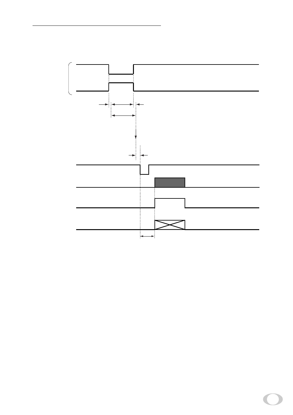
( 4 ) PW SR (Pulse width trigger SYNC-RESET)
The trigger input to the CC1 of the DIGITAL terminal develops 1 frame images.
(4. 1) 1 Pulse Width Trigger SYNC-RESET Picture Output Timing
*1: Externally input signal
*2: Exposure time = Trigger pulse width + 6
µ
s
(Valid trigger pulse width is 2
µ
s or greater for external trigger shutter operation.)
*3: VD is generated after 0 to 2H following the completion of the exposure period and the video is synchro-
nized to this and output.
Note:
When the next trigger is input before completion of the output of the video corresponding to the trig-
ger, there will be an effect on the video.
About 1
µ
s
About 7
µ
s
Exposure completion
0 to 2H
Trigger*
1
Negative polarity mode
Positive polarity mode
Exposure period*
2
(Internal VD)*
3
RGB data
(video interval image)
FVAL
LVAL,
DVAL
58H (Partial scanning OFF)
56H (Partial scanning 30fps)
78H (Partial scanning 40fps)
- PDR-3310 (2 pages)
- V Series (2 pages)
- CSGS15BC23 (56 pages)
- HIGH RESOLUTION CMOS CAMERA CSB1100F (2 pages)
- IK-VR01A (19 pages)
- T10 (59 pages)
- IK-DP01A (2 pages)
- IK-TF2 (32 pages)
- PDR-T20 (70 pages)
- PDR-M60 (64 pages)
- IK-53N (22 pages)
- IK-1000 (2 pages)
- TELI CS3950DIF (24 pages)
- PDR-M81 (142 pages)
- IK-644A (9 pages)
- pmn (60 pages)
- PDR-M700 (2 pages)
- IK-DP30A (2 pages)
- IK-WB11 (8 pages)
- TELI CS5260BDP (5 pages)
- TLP848 (12 pages)
- IK-65WDA (32 pages)
- IK-6550A (2 pages)
- PDR-M11 (272 pages)
- IK-52V (2 pages)
- PDR-M70 (2 pages)
- USB Webcam (17 pages)
- CSB1100CL-10 (16 pages)
- IK-6410A (16 pages)
- IK-TF7C (36 pages)
- PDR-M71 (140 pages)
- IK-629A (9 pages)
- IK-WB15AIP (2 pages)
- IK-WR01A (16 pages)
- IK-DF01A (16 pages)
- IK-6210A (2 pages)
- PDR-M65 (109 pages)
- CCD IK-6400A (4 pages)
- CS6940CL (17 pages)
- IK-TF5 (36 pages)
- CCD Monochrome Camera IK-539A (10 pages)
- CMOS Color Camera IK-HR1D (28 pages)
- PDR-M5 (120 pages)
- CS3950D (23 pages)