Toshiba ETB003Z User Manual
Page 10
E6581339⑤
9
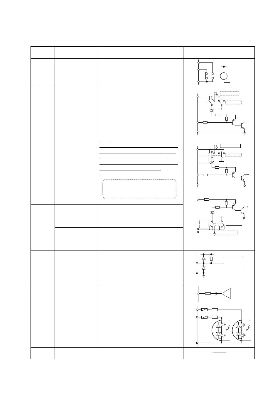
< Input/output terminal interface >
Terminal
symbol
Function Electrical
specification Internal
circuit
R1A
R1B
R1C
Relay contact
point output
Configuration of 1C contact point
250Vac - 2A (cosφ=1)
250Vac - 1A (cosφ=0.4)
30Vdc - 1A
R1A
R1B
R1C
Ry
LI1
LI2
LI3
LI4
Contact point
input Changeover
of sink or source
No voltage contact input
24Vdc - 5mA
Sink input (common voltage 24V)
ON :less than 10Vdc
OFF :16Vdc or more
Source input
ON :11Vdc or more
OFF :less than 5Vdc
Note:
Even when an external power supply
is used (in sink logic mode i.e. when
SINK(PLC) is selected), connect
the reference potential-side (0V side)
cable from the power supply
to the CC terminal.
24V power supply
24Vdc power output (when SW1 is
in any position other than PLC)
24V internal output terminal
24Vdc - 60mA max
PLC/
P24
Common terminal
for external
power supply
If SW1 is turned to the PLC position,
this terminal can be used as a
common terminal when an external
power supply is used.
SINK Logic(SW =SINK(INT))
SW
2.2k ohm
2.2k ohm
CC
LI1
LI2
LI3
LI4
SOURCE
P24/
PLC
SINK(PLC)
SINK
(INT)
P24
SINK Logic (SW =SINK(PLC))
SW
2.2k ohm
2.2k ohm
CC
LI1
LI2
LI3
LI4
SOURCE
P24/
PLC
SINK(PLC)
SINK
(INT)
P24
SOURCE Logic (SW =SOURCE)
SW
SOURCE
2.2k ohm
P24/
PLC
2.2k ohm
CC
LI1
LI2
LI3
LI4
SINK(PLC)
SINK
(INT)
P24
TH1+
TH1-
Thermal trip input
The resistance between TH1+ and
TH1-
Tripping value: about under 70 ohm
or about over 2.5k
ohm
Reset value: about 1.6k ohm
Voltage
detection
circuit
3k ohm
TH1+
P5
TH1-
N10
-10V power upply
DC-10V - 10mA
N
10
OP
100 ohm
OUT3
OUT4
NO1
Multifunction
programmable
open collector
output.
Open collector output
Drive current
External power supply used: 50mA
Internal power supply used: 20mA
Drive voltage
12V min - 30V max
Isolated other circuit.
20 ohm
OUT3
OUT4
20 ohm
NO1
CC
Common to
input/output
Digital signal equipotential (0V)
erminal for the control circuit
Lan current signal.
Chose low current contacts to
avoid poor attaching.