2 setup and required equipment – Texas Instruments HPL-D SLLU064A User Manual
Page 14
2 Setup and Required Equipment
2-2
DA
T
A
,
D
A
T
A
A
m
pl
it
ude
:
400
mV
Of
fs
et
:
0.
0
V
DA
T
A
,
D
A
TA
A
m
pl
itu
d
e:
400
m
V
O
ffs
et:
0.0
V
`
U1
1
J1
8
J2
0
VT
E
R
M
GN
D
J4
J3
J1
J2
J1
5
J16
J1
4
J1
3
W1
2
VC
C
W1
1
2D
E
VC
C
1D
E
J1
9
VC
C
0
1
J1
1
J1
2
W9
W1
0
3D
E
VC
C
4D
E
VC
C
J9
J1
0
W6
W5
W7
W
8
VC
C
S4
0
VC
C
VC
C
S4
1
VC
C
S3
0
S
3
1
J7
J8
J6
J5
J1
7
VC
C
VC
C
W2
W1
W4
W3
VC
C
S1
0
S
1
1
VC
C
V
C
C
S2
0
S2
1
DATA, DATA
Amplitude: 400 mV
Offset: 0.0 V
DATA, DATA
Amplitude: 400 mV
Offset: 0.0 V
Power Supply #1
Power Supply #2
3.3V
1.2V
+
-
+
-
SCOPE
(internally
terminated
50 to GND)
Ω
Ω
Ω
Ω
GN
D
GN
D
GN
D
GN
D
GN
D
GN
D
GN
D
GN
D
GN
D
GN
D
GN
D
GN
D
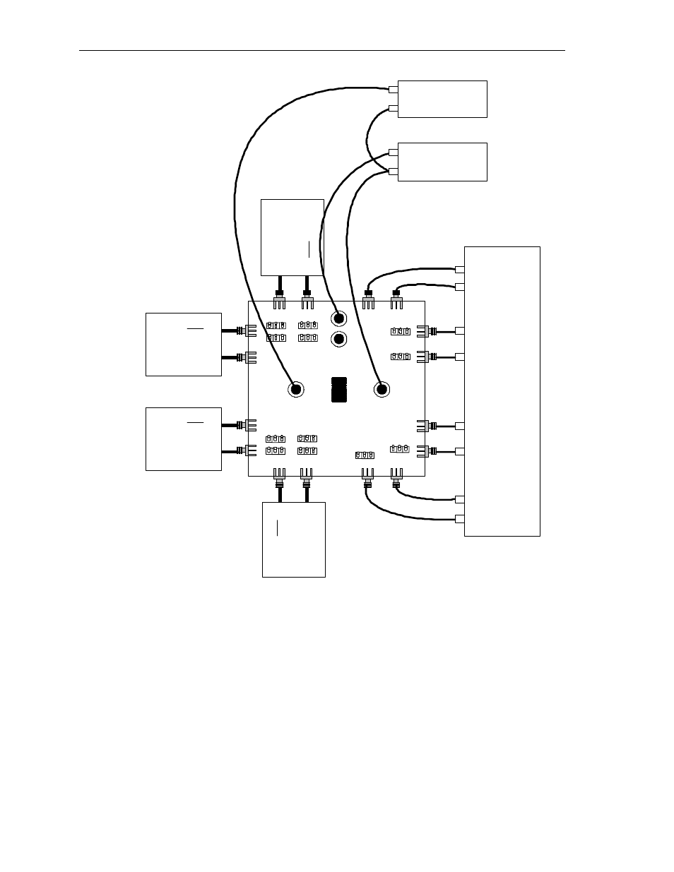
Figure 2-1. EVM Power Connections for Either SN65LVDS125A or SN65LVDS250
Evaluation.
Many possible configurations for the 4x4 crosspoint switches are made
available. Table 2-1 provides a description of the different functions and
the required selector settings.