Installation- electrical, Electrical system – Trane GSSD User Manual
Page 12
12
.
Table 1: Electrical Data
Unit Model: GSSD
024
030
036
042
048
060
072
Electrical
Volts-60HZ/1Phase
208-230
208-230
208-230
208-230
208-230
208-230
208-230
Compressor RLA
11.4
13.6
15
18.4
20.4
28
32.1
Compressor LRA
56
67
73
95
109
169
169
Blower Motor RLA
3
5
5.6
5.6
5.6
7.4
7.4
Min. Circuit Amp.
14.7
17.4
19.2
23.4
25.9
35.4
40.5
Max Fuse Size
25
30
30
40
45
60
70
Desuperhtr Pump RLA
0.40
0.40
0.40
0.40
0.40
0.40
0.40
Installation- Electrical
Note: 208/230 volt equipment is designed to operate between 197 and 253 volts. Operation outside of these
ranges is likely to adversely affect the service life of the equipment.
Electrical System
The factory tested and installed control
box contains all of the necessary de-
vices to control unit operation in both
the heating and cooling mode. A re-
mote wall thermostat is necessary for
the control of the unit operation.
See
General Information for thermostat in-
formation
.
The nameplate provides information
for the application of either time delay
fuses or HACR circuit breakers for
branch circuit protection from the pri-
mary source of power.
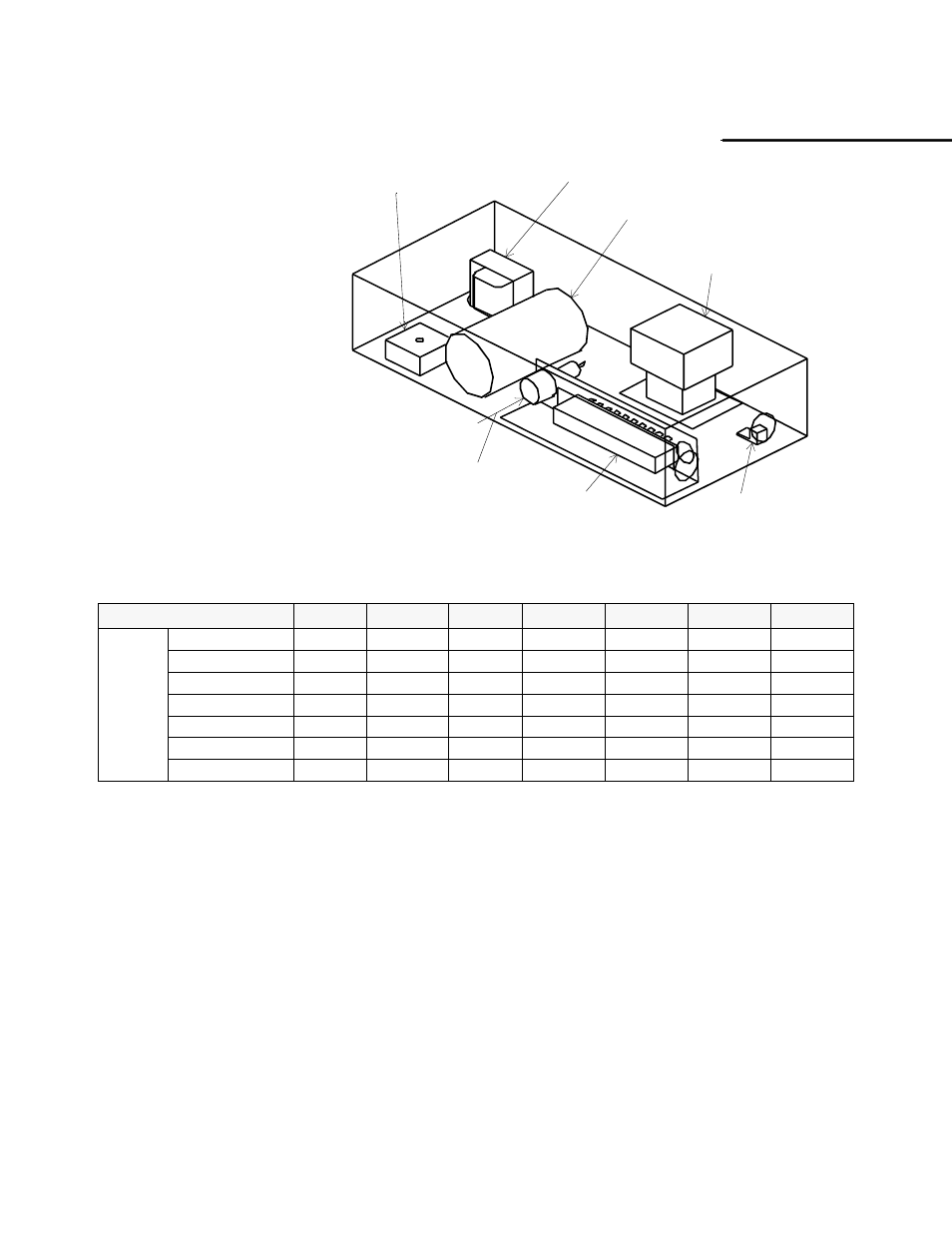
See Figure 6 for
component specifications.
24VAC ENERGY LIMITING CLASS II
75VA BREAKER TYPE TRANSFORMER
3 POLE-24VAC
COMPRESSOR CONTACTOR
ALUMINUM
GROUND TERMINAL
10 POLE TERMINAL
STRIP; 20A-250V
FUSE; 2 AMP
480V
COMPRESSOR RUN CAPACITOR
370V
LOCKOUT
RELAY; 24VAC
IF DESUPERHEATER
IS USED, THE FUSE
IS SHIPPED IN A CLOTH
BAG
Figure 6: Electric component location.