Installation-water connections, Location consideration, Water connections – Trane GSSD User Manual
Page 10: Refrigeration connections
10
Installation-Water Connections
Location Consideration
!
Unit should be placed on a level
surface in a indoor protected area.
Units should not be installed or
stored in an exterior environment.
!
There should be approximately 2
to 3 feet of clearance available for
accessing the unit for service.
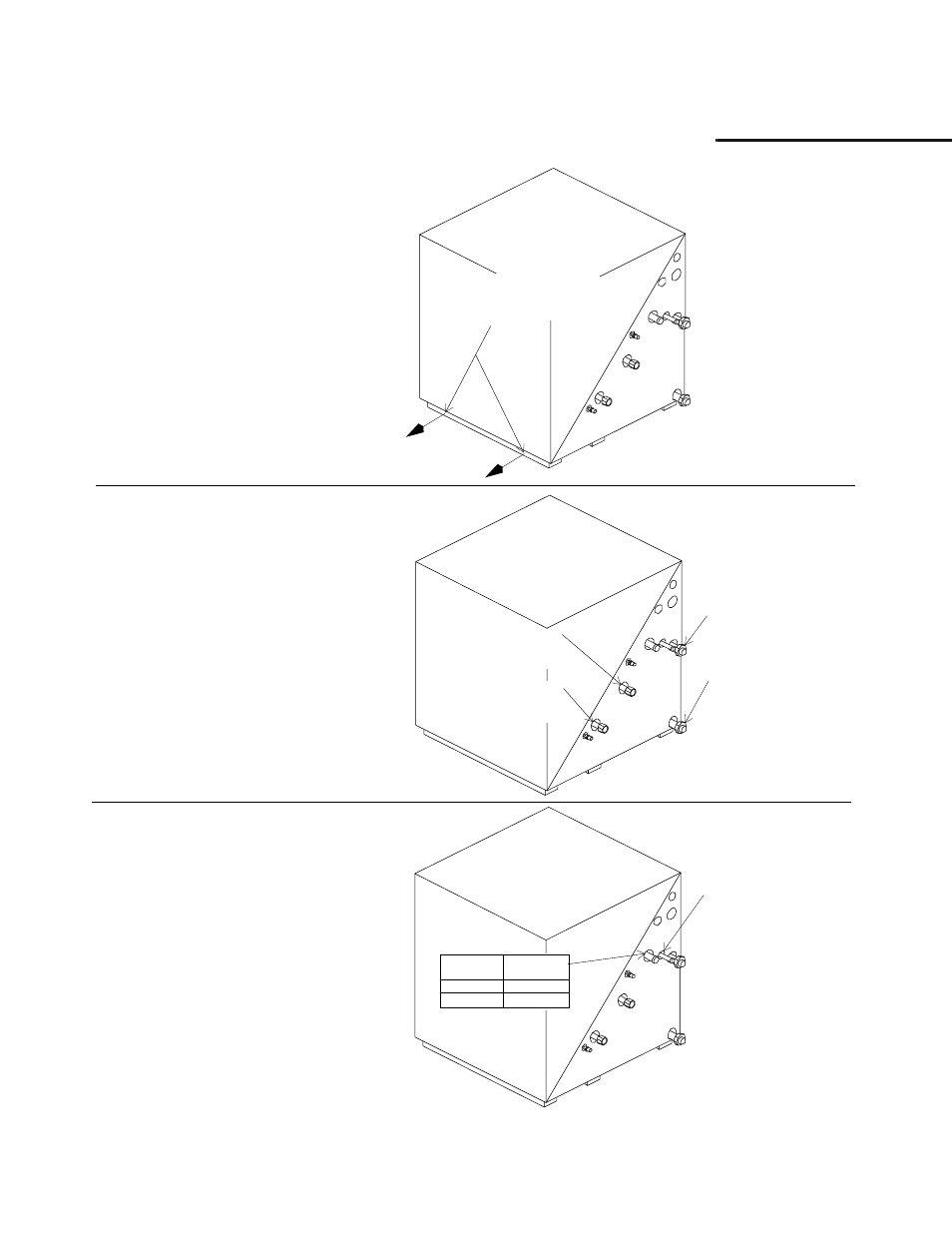
Accessiblity into unit is made by re-
moving (2) two screws at the base of
the system.
(See Figure 2).
The top half of the cube then lifts off.
Remove these two
screws for internal unit
maintenance.
Figure 2: Unit access.
Water-out
1” Female NPT
Water-in
1” Female NPT
Desuperheater
Water-in
1/2” Female NPT
Desuperheater
Water-out
1/2” Female NPT
Figure 3: Water hook-up locations.
Unit Size
024
030-072
Suction
Line (O.D.)
3/4”
7/8”
Liquid Line
1/2” O.D.
Figure 4: Liquid and suction lines.
Water Connections
The loop water connections brought to
the unit should be 1-inch male national
pipe threads.
The desuperheater (optional) connec-
tions should be 1/2-inch male national
pipe threads.
(See Figure 3 for water hook-up loca-
tions)
.
Refrigeration Connections
The refrigeration piping connections
are copper stub-outs. All refrigeration
connections are to be soldered into the
unit. It may be necessary to provide an
adapter to connect to the chosen air
handler.
(See Figure 4 for location and
sizes).
Note:
All refrigeration piping between the air
handler and the heat pump should be ade-
quately insulated. Water piping should also
be insulated to reduce heat transfer and the
forming of condensation.