1 power connections, Details – Texas Instruments SLOU082 User Manual
Page 21
Using The TPA032D03 Class-D EVM Stand-Alone
3-7
Details
3.7
Using The TPA032D03 Class-D EVM Stand-Alone
Using the TPA032D03 mono class-D audio power amplifier evaluation module
stand-alone is much the same as using it with the platform. The same 9-V to
14-V power supply range and the isolated OUT+ and OUT– lines for BTL
operation requirements exist. Inserting a plug into the EVM headphone jack
switches the EVM to the headphone mode and shuts down the class-D
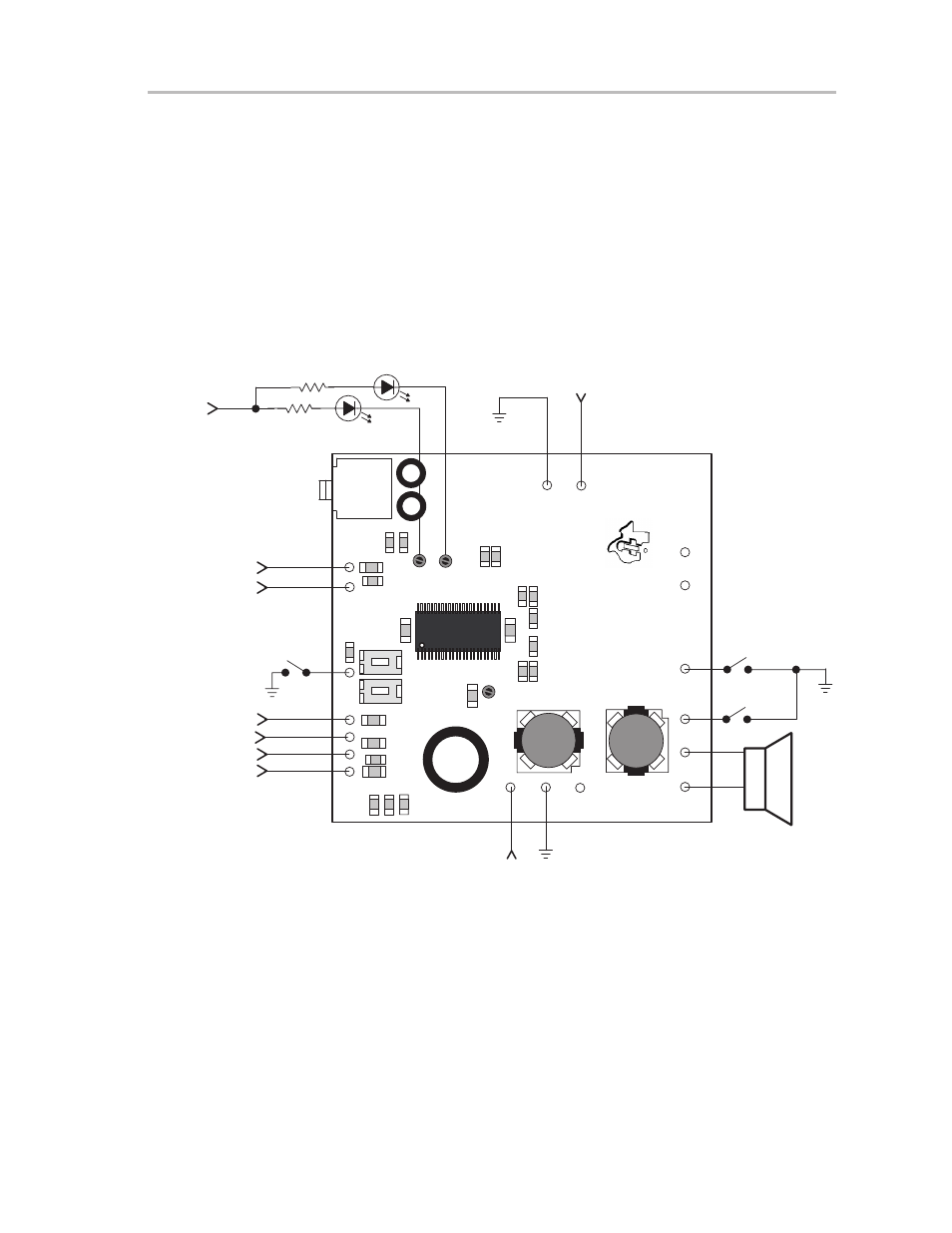
amplifier section. Figure 3–3 shows the connections that are required for
operation (with the exception of the fault monitor circuit, which is optional). The
discussion in this section is in reference to this figure unless otherwise noted.
Figure 3–3. TPA032D03 Class-D EVM Stand-Alone Connections for Mono BTL Output
5 V
12 V
Audio
Line
Inputs
LED 0
R
Shutdown
Mute
R
5 V
LED 1
Fault
Monitor
U1
C1
1
R6
R5
SD
Mute
OUT+
OUT–
GND
VDD
R3
GND
–IN+
GND
S1
Mute
S2
SD
C16
L2
TP1
TP3
TP2
+
VCC
R14
C2
R13
L1
C5
GND
VCC
T
exas
2000
Instruments
RHP
SLOP310
TPA032D03 EVM Board
C19
C20
Mode
LHP
J1
R2
C4
C3
R1
C1
R4
R12
R1
1
C12
R10
C18
R9
R8
R7
C17
Headphone
Output Jack
Left HP
Input
Right HP
Input
Mode
Note:
Capacitor C11 is optional (not assembled) and a location for it on the EVM PCB has been provided to increase design
flexibility and allow decoupling capacitance to be added.
3.7.1
Power Connections
Power must be connected to both the VCC and VDD module pins. Power
supply ground can be connected to any module ground pin, although best
results are achieved if power supply grounds are connected to the pins
adjacent to the VCC and VDD module pins. The ground and power wires
should be twisted to reduce inductance and noise pickup if they are long.