Fireplace framing specifications – TOA Electronics DIRECT VENT 600 User Manual
Page 7
7
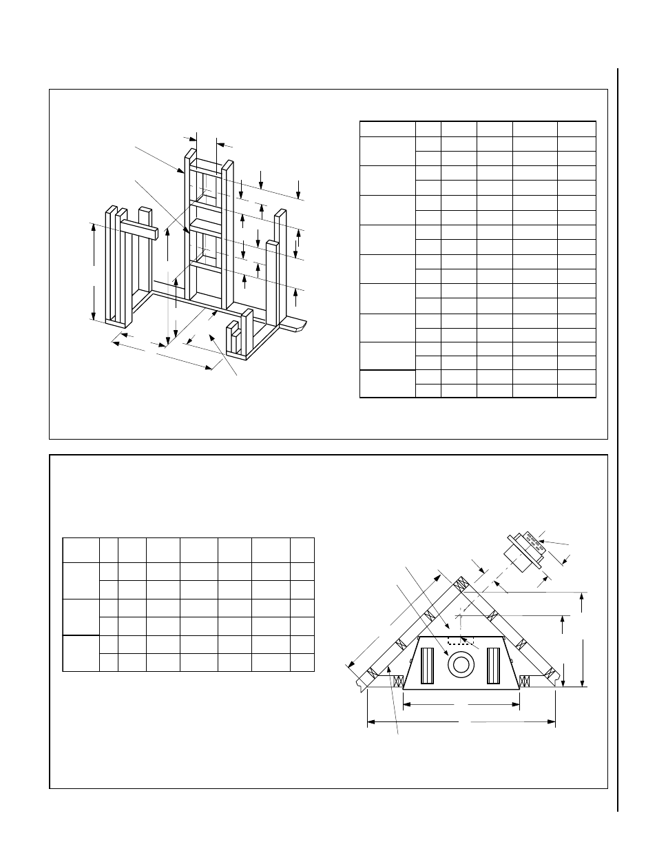
NOTE: DIAGRAMS & ILLUSTRATIONS NOT TO SCALE.
l
e
d
o
M
.
o
N
A
B
C
D
E
F
0
0
5
-
D
0
0
5
-
T
D
0
0
5
-
R
D
.
n
i
8
/
1
5
3
2
/
1
7
5
8
/
5
0
4
6
1
/
3
9
1
4
/
3
8
2
8
/
1
6
m
m
2
9
8
1
6
4
1
2
3
0
1
7
8
4
0
3
7
6
5
1
0
0
6
-
D
0
0
6
-
T
D
0
0
6
-
R
D
.
n
i
8
/
1
0
4
6
1
/
3
1
6
2
3
/
1
3
4
6
1
/
3
9
1
6
1
/
1
1
0
3
8
/
7
7
m
m
9
1
0
1
4
5
5
1
1
0
1
1
7
8
4
9
7
7
0
0
2
0
0
8
-
D
0
0
8
-
T
D
0
0
8
-
R
D
.
n
i
8
/
1
5
4
8
/
3
6
6
6
1
/
5
1
6
4
6
1
/
3
9
1
6
1
/
3
3
3
4
/
3
9
m
m
6
4
1
1
6
8
6
1
2
9
1
1
7
8
4
3
4
8
8
4
2
C
Back wall of chase/enclosure
(including any finishing materials)
a
7 (178)
b
Note-
Venting requirements for rear vent applications in corner
installations -
- the the round termination (SV4.5HTR) may not be used
- the horizontal vent length “a” to “b,” must not exceed 28
inches (711 mm)
Inches
(millimeters)
*These dimensions occur when one 45
degree elbow is connected directly to the
appliance collar.
D and DR units
D and DT units
*D
E
*F
A
B
.
o
N
l
e
d
o
M
A
B
C
D
0
0
5
-
D
.
n
i
4
/
1
5
3
4
/
1
5
3
6
1
/
1
1
1
2
8
/
1
9
3
m
m
5
9
8
5
9
8
1
5
5
4
9
9
0
0
5
-
T
D
.
n
i
4
/
1
5
3
4
/
1
5
3
-
-
-
-
8
/
1
9
3
m
m
5
9
8
5
9
8
-
-
-
-
4
9
9
0
0
5
-
R
D
.
n
i
4
/
1
5
3
4
/
1
5
3
6
1
/
1
1
1
2
-
-
-
-
m
m
5
9
8
5
9
8
1
5
5
-
-
-
-
0
0
6
-
D
.
n
i
4
/
1
0
4
4
/
1
0
4
6
1
/
1
1
6
2
8
/
1
4
4
m
m
2
2
0
1
2
2
0
1
8
7
6
1
2
1
1
0
0
6
-
T
D
.
n
i
4
/
1
0
4
4
/
1
0
4
-
-
-
-
8
/
1
4
4
m
m
2
2
0
1
2
2
0
1
-
-
-
-
1
2
1
1
0
0
6
-
R
D
.
n
i
4
/
1
0
4
4
/
1
0
4
6
1
/
1
1
6
2
-
-
-
-
m
m
2
2
0
1
2
2
0
1
8
7
6
-
-
-
-
0
0
8
-
D
.
n
i
4
/
1
5
4
4
/
1
0
4
6
1
/
1
1
6
2
8
/
1
4
4
m
m
9
4
1
1
2
2
0
1
8
7
6
1
2
1
1
0
0
8
-
T
D
.
n
i
4
/
1
5
4
4
/
1
0
4
-
-
-
-
8
/
1
4
4
m
m
9
4
1
1
2
2
0
1
-
-
-
-
1
2
1
1
0
0
8
-
R
D
.
n
i
4
/
1
5
4
4
/
1
0
4
6
1
/
1
1
6
2
-
-
-
-
m
m
9
4
1
1
2
2
0
1
8
7
6
-
-
-
-
A
B
D
7
(178)
5
¹⁄₈
12
¹⁄₈
(308)
10
¹⁄₂
(
267
)
C
VENT FRAMING -
TOP VENT WITH ONE
90
°
ELBOW
VENT FRAMING -
REAR VENT WITH
NO ELBOWS
Framing should be constructed
of 2x4 or larger lumber.
Inches (mm)
(130)
5
¹⁄₈
(130)
7
(178)
16” (406mm) is the required framing depth dimension when
the finish material (drywall) thickness is 1/2 in. (13mm).
¹⁄₂ A
**FRAMING WITH SQUARE HORIZONTAL TERMINATIONS (SV4.5HTSS or SV4.5HTS)
AND ROUND HORIZONTAL TERMINATION (SV4.5HTR)
** See the horizontal venting Figures 33 and 34 on page 16 for restrictions on the use of the
round termination (SV4.5HTR).
12
¹⁄₈
(308)
16
(406)
Figure 9
Figure 10 Corner Framing with Square Termination (SV4.5HTS)
Framing Dimensions
FIREPLACE FRAMING SPECIFICATIONS