TOA Electronics DIRECT VENT 600 User Manual
Page 4
4
NOTE: DIAGRAMS & ILLUSTRATIONS NOT TO SCALE.
K
C
A
B
)
m
m
3
1
(
.
n
i
2
/
1
s
r
e
c
a
p
s
)
m
m
0
(
.
n
i
0
S
E
D
I
S
*
*
)
m
m
3
1
(
.
n
i
2
/
1
s
r
e
c
a
p
s
)
m
m
0
(
.
n
i
0
S
R
E
C
A
P
S
P
O
T
)
m
m
0
(
.
n
i
0
R
O
O
L
F
)
m
m
0
(
.
n
i
0
f
o
m
o
t
t
o
B
m
o
r
F
g
n
il
i
e
C
o
t
t
i
n
U
)
m
m
6
2
6
1
(
.
n
i
4
6
T
N
E
V
*
)
m
m
4
.
5
2
(
.
n
i
1
S
E
C
N
A
R
A
E
L
C
E
C
I
V
R
E
S
T
N
O
R
F
)
s
r
e
t
e
m
9
.
0
(
.
t
e
e
F
3
.
o
N
l
e
d
o
M
)
m
m
(
s
e
h
c
n
i
t
h
g
i
e
H
f
l
e
h
S
w
o
b
l
E
e
e
r
g
e
D
0
9
e
n
O
h
t
i
w
-
t
n
e
V
p
o
T
k
c
a
B
e
h
t
t
u
O
t
h
g
i
a
r
t
S
-
t
n
e
V
r
a
e
R
t
n
e
V
e
r
u
c
e
S
x
e
l
F
e
r
u
c
e
S
t
n
e
V
e
r
u
c
e
S
x
e
l
F
e
r
u
c
e
S
0
0
5
-
D
8
/
1
6
4
)
2
7
1
1
(
8
/
7
7
4
)
6
1
2
1
(
)
5
9
8
(
4
/
1
5
3
)
5
9
8
(
4
/
1
5
3
0
0
5
-
T
D
)
2
7
1
1
(
8
/
1
6
4
)
6
1
2
1
(
8
/
7
7
4
A
/
N
A
/
N
0
0
5
-
R
D
A
/
N
A
/
N
)
5
9
8
(
4
/
1
5
3
)
5
9
8
(
4
/
1
5
3
0
0
8
-
D
,
0
0
6
-
D
)
8
9
2
1
(
8
/
1
1
5
)
3
4
3
1
(
8
/
7
2
5
)
2
2
0
1
(
4
/
1
0
4
)
2
2
0
1
(
4
/
1
0
4
0
0
8
-
T
D
,
0
0
6
-
T
D
)
8
9
2
1
(
8
/
1
1
5
)
3
4
3
1
(
8
/
7
2
5
A
/
N
A
/
N
0
0
8
-
R
D
,
0
0
6
-
R
D
A
/
N
A
/
N
)
2
2
0
1
(
4
/
1
0
4
)
2
2
0
1
(
4
/
1
0
4
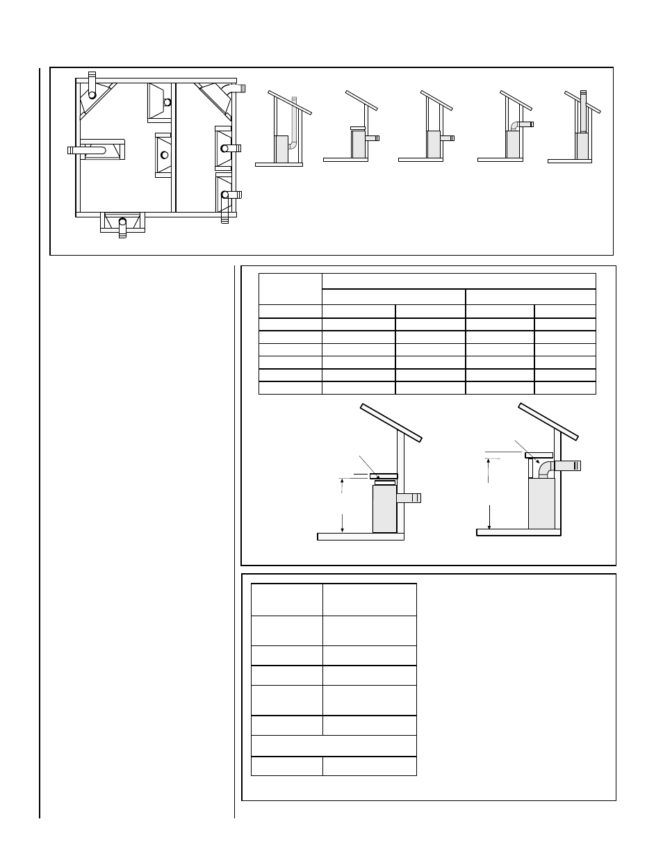
Shelf Above Fireplace With Rear Venting
Do not insulate the
space between the
appliance and the
area above it.
Shelf Height
(
see table)
Shelf Height
(
see table)
Do not insulate the
space between the
appliance and the
area above it.
Shelf Above Fireplace With Top Venting
(Rear Vent Application
HORIZONTAL VENT
without a chase)
HORIZONTAL VENT
(Rear Vent Application
With a chase)
HORIZONTAL VENT
(Top Vent
Application)
VERTICAL VENT
(Top Vent
Application)
(Rear Vent
VERTICAL VENT
Application)
APPLICA
TION
REAR VENT
APPLICA
TION
TOP VENT
APPLICATION
TOP VENT
REAR VENT
APPLICA
TION
TOP VENT
APPLICA
TION
RECESSED
INSTALLATION
TOP VENT
APPLICATION
APPLICA
TION
TOP VENT
APPLICA
TION
TOP VENT
Figure 2
Figure 3
*Note: 3 in. (75 mm) above any horizontal/
inclined vent component.
**Note: The nailing flange and the cabinet
surfaces directly adjacent to the framing mem-
ber attached to the nailing flange, are exempt
from the 1/2" clearance to combustibles de-
fined for the rest of the cabinet sides and back.
Table 2
Typical Locations
The location should also be free of electrical,
plumbing or other heating/air conditioning duct-
ing. These direct vent appliances are uniquely
suited for installations requiring a utility shelf
positioned directly above the fireplace. Utility
shelves like these are commonly used for locat-
ing television sets and decorative plants.
To provide for the lowest possible shelf surface
use the alternate rear vent outlet with attached
venting routed in a way to minimize obstructions
to the use of the space above the appliance. Do
not insulate the space between the appliance
and the area above it. See
Figure 3. The
minimum height from the base of the appliance
to the underside of combustible materials used
to construct a utility shelf in this fashion is shown
in the table in
Figure 3.
The appliance should be mounted on a fully
supported base extending the full width and
depth of the unit. The appliance may be located
on or near conventional construction materi-
als. However, if installed on combustible ma-
terials, such as carpeting, vinyl tile, etc., a
metal or wood barrier covering the entire bot-
tom surface must be used.
APPLIANCE AND VENT CLEARANCES
These appliances are approved with zero clear-
ance from spacers to combustible materials on
all sides (as detailed in
Table 2 ), with the
following exception: When the unit is installed
with one side flush with a perpendictular side
wall, the wall perpendicular to the opposite side
of the appliance front face must not extend
more than five inches beyond the front edge of
the unit. In addition, when the unit is recessed,
the side walls surrounding the unit must not
extend more than five inches beyond the front
edge of the unit. Refer to
Figure 2.