Assembly, Continuous duty solenoid switch – Tiger Products Co., Ltd JOHN DEERE 5101E User Manual
Page 45
ASSEMBLY
Assembly Section 2-19
CONTINUOUS DUTY SOLENOID SWITCH
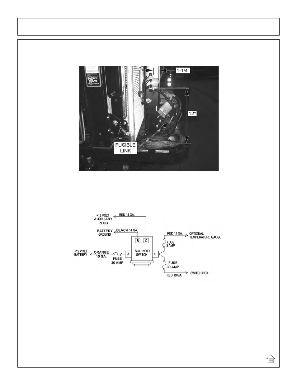
To mount the solenoid switch, drill 1/4” holes to match as necessary in location shown below.
Secure with provided 3/8” x 1” capscrews, lockwashers, and hex nuts.
Route wires to and from the Continuous Duty Solenoid Switch as shown below.
A.) ORANGE 10 GA. wire from terminal (A) to +12V battery fusible link.
B.) RED 14 GA. wire from terminal (B) to tractor plug in cab.
C.) BLACK 14 GA. wire from terminal (C) to -12V battery post.
D.) RED 10 GA. wire from terminal (D) to switch box.
E.) RED 14 GA. wire from terminal (D) to temperature gauge. (optional).
(ASM-T3F-0023)
This manual is related to the following products: