Refrigerant piping and evacuating, Refrigerant piping – Toshiba RAV-SM2242DT-E User Manual
Page 23
– 22 –
Concealed Duct High Static Pressure
Installation Manual
EN
7
REFRIGERANT PIPING AND EVACUATING
Refrigerant Piping
1. If the outdoor units are to be mounted on a wall,
make sure that the supporting platform is sufficiently
strong. The platform should be designed and
manufactured to maintain its strength over a long
period of time, and sufficient consideration should
be given to ensuring that the outdoor unit will not fall.
2. Use general copper pipes with a wall thickness of 0.8
mm for Ø12.7 mm, and with a wall thickness of 1.0
mm for Ø28.6 mm (half hard).
Do not use any copper pipes with a wall thickness
less than these thicknesses.
3. Flare nut and flare works are also different from those of
the conventional refrigerant.
Take out the flare nut attached to the main unit of the air
conditioner, and use it.
REQUIREMENT
When the refrigerant pipe is long, provide support brackets at
intervals of 2.5 to 3m to clamp the refrigerant pipe. Otherwise,
abnormal sound may be generated.
CAUTION
IMPORTANT 4 POINTS FOR PIPING WORK
1. Remove dust and moisture from the inside of the
connecting pipes.
2. Tight connection (between pipes and unit)
3. Evacuate the air in the connecting pipes using
VACUUM PUMP.
4. Check the gas leakage. (Connected points)
Pipe size
Liquid side refrigerant pipe
connection
Permissible Piping Length and Height
Difference
They vary according to the outdoor unit.
For details, refer to the Installation Manual attached to the
outdoor unit.
Flaring
• Cut the pipe with a pipe cutter.
Remove burrs completely.
Remaining burrs may cause gas leakage.
• Insert a flare nut into the pipe, and flare the pipe.
As the flaring sizes of R410A differ from those of
refrigerant R22, the flare tools newly manufactured for
R410A are recommended.
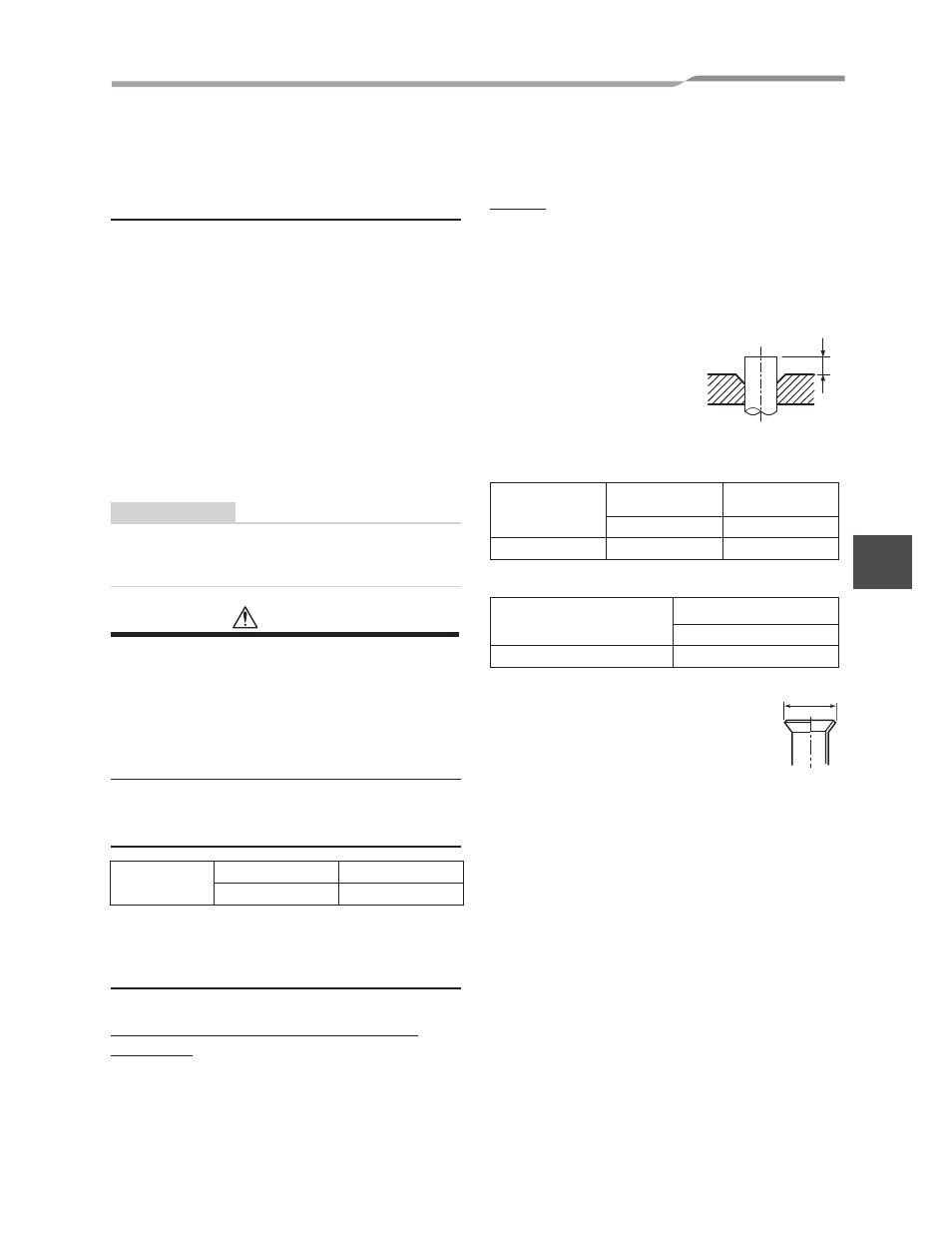
However, the conventional tools can
be used by adjusting projection
margin of the copper pipe.
▼
Projection margin in flaring: B (Unit: mm)
Rigid (Clutch type)
▼
Flaring dia. meter size: A (Unit: mm)
* In case of flaring for R410A with the
conventional flare tool, pull it out approx.
0.5 mm more than that for R22 to adjust to the
specified flare size.
The copper pipe gauge is useful for adjusting
projection margin size.
Pipe size
Gas side
28.6 mm
Liquid side
12.7 mm
Outer dia. of
copper pipe
R410A tool used
Conventional tool
used
R410A
R410A
12.7
0 to 0.5
1.5 to 2.0
Outer dia. of copper pipe
A
+0
-0.02" (–0.4)
R410A
12.7
16.6
B
A
22-EN