Telex PW24-2 User Manual
Page 4
microphone starts recording at the same time. The transmitter must be
turned on and in standby mode.
19) A +5V signal on the Auto Talk line means the microphone is off.
20) 0V or ground on the Auto Talk line turns on the microphone
INSTALLATION
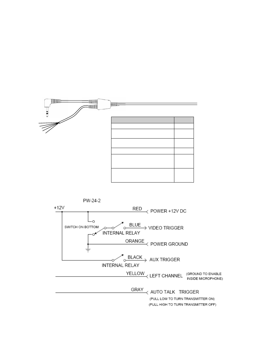
1. Wire the un-terminated signal wires to the control unit according to the signal chart. A 5
Amp fast blow fuse is recommend in the 12VDC power supply line to protect the
equipment.
Description
Color
Power +12V DC
Red
Video Trigger
(Ground = Transmitter On)
Blue
Left Channel (Ground to enable
Inside Microphone)
Yellow
Power Ground
Orange
12 FT
Audio In
Un-terminated wires
AUX (Panic) Trigger
12V+ DC Output when EMG
button is pushed
Black
Auto Talk Trigger
5V+ DC to 0V to turn on mic
0V to 5V+DC to turn off mic
Gray
Revision B
Page 4 of 8
10/11/06