Transcend Information Secure Digital Card TS2GSD150 User Manual
Page 11
T
T
T
S
S
S
2
2
2
G
G
G
S
S
S
D
D
D
1
1
1
5
5
5
0
0
0
2GB 150x Secure Digital Card
Transcend Information Inc.
11
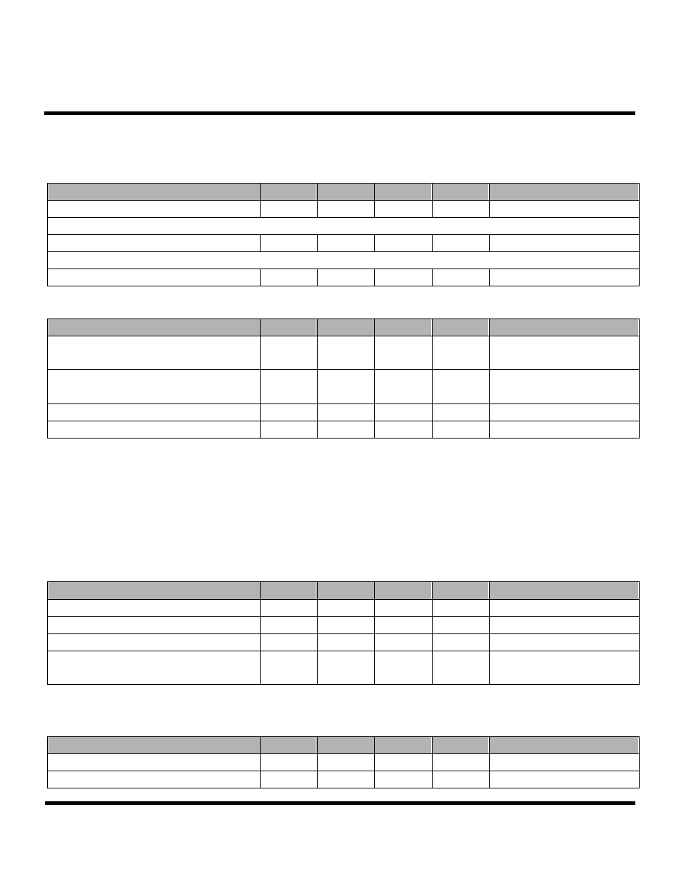
AC/DC Character
• General
Parameter
Symbol
Min.
Max.
Unit
Remark
Peak voltage on all lines
-0.3 VDD+0.3
V
All Inputs
Input Leakage Current
-10 10 µA
All Outputs
Output Leakage Current
-10 10 µA
• Power Supply Voltage
Parameter
Symbol
Min.
Max.
Unit
Remark
Supply voltage
V
DD
2.0 3.6 V
CMD0,
15,55,ACMD41
commands
Supply voltage specified in OCR register
2.7
3.6
V
Except CMD0, 15,55,
ACMD41 commands
Supply voltage differentials (V
SS1
, V
SS2
) -0.3
0.3 V
Power up time
250
ms
From 0v to V
DD
Min.
•
Bus Signal Line Load
The total capacitance C
L
the CLK line of the SD Memory Card bus is the sum of the bus master capacitance C
HOST
, the bus
capacitance C
BUS
itself and the capacitance C
CARD
of each card connected to this line:
C
L
= C
HOST
+ C
BUS
+
Ν*C
CARD
Parameter
Symbol
Min.
Max.
Unit
Remark
Bus signal line capacitance
C
L
100
pF
f
PP
≤ 20 MHz, 7 cards
Single card capacitance
C
CARD
10
pF
Maximum signal line inductance
16
nH
f
PP
≤ 20 MHz
Pull-up resistance inside card (pin1)
R
DAT3
10 90 k
Ω
May be used for card
detection
Note that the total capacitance of CMD and DAT lines will be consist of C
HOST
, C
BUS
and one C
CARD
only since they are
connected separately to the SD Memory Card host.
Parameter
Symbol
Min.
Max.
Unit
Remark
Pull-up resistance
R
CMD
, R
DAT
10 100 k
Ω
To prevent bus floating
Bus signal line capacitance
C
L
250
pF
f
PP
≤ 5 MHz, 21 cards