Technical overview, Block diagram & operational details – QSC Audio PL224A User Manual
Page 28
TECHNICAL OVERVIEW:
BLOCK DIAGRAM & OPERATIONAL DETAILS
An impressive amount of
technology is packed "under the
hood" of a PL2A amplifier.
Thousands of watts of power
flow inches away from state-
of-the-art low noise inputs.
Precise circuit layout and
thorough protection assure
that all of this activity occurs
smoothly and safely. So, what
actually happens when you
turn on the power switch?
Soft Start Sequence. The
first task is to charge the
primary energy reservoir
without drawing a large surge
current. A special inrush limiter
allows just enough current to
charge the energy bank in
three seconds. Meanwhile, a
low-power switching supply
provides power to start up the
main supply. After three
seconds, a relay bypasses the
inrush limiting and full power
operation is enabled. The
audio circuitry mutes for one
second to eliminate start-up
thumps. When the red
CLIP
lights go out, the amplifier is
ready for action.
PowerWave™
Technology. High current switching devices draw over 10,000 watts of peak power from the main energy reservoir, which is
replenished directly from the AC line for maximum stiffness. Conventional amplifiers must isolate the energy bank with a large AC transformer,
which weakens the flow of current, allows greater sag under load, and produces hum. The PowerWave
supply performs voltage conversion at
a very high frequency, allowing better coupling through a much smaller isolation transformer.
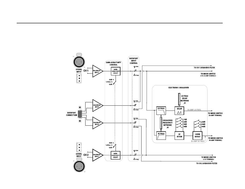
Block diagram of audio path in a PL2A amplifier
28