Appliance preparation, Caution – Quadra-Fire Expression 36 QV36A-FB User Manual
Page 20
Quadra-Fire • Expression 36 (QV36A-FB) • 2062-900 Rev. S • 11/11
20
7
7
Appliance Preparation
A. Removing Non-combustible Facing Mate-
rial Assembly
The non-combustible assembly is located on the back
side of appliance.
CAUTION
Handle with care
• Non-combustible material may be damaged if dropped.
• Hold non-combustible pieces in place.
• Remove and save two screws from upper bracket.
• Remove non-combustible pieces.
• Remove and save three screws from lower bracket.
• Discard brackets.
• Replace screws in holes where brackets were attached
to appliance.
B. Installing the Optional Heat-Zone
®
Gas
Kit
Before installing fi nishing materials, use these instructions to
attach the Heat-Zone
®
Gas kit to the top of the QV36A-FB.
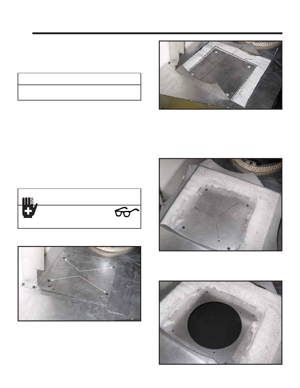
REMOVE SCREWS
1. Remove the four screws that attach the Heat Zone
®
Cover Plate to the top of the appliance.
Figure 7.1. Remove Screws.
2. Bend the four pre-cut tabs up to expose the top of the
appliance. Place the Heat-Zone
®
cover plate on the
insulation inside the unit centered between the three
pre-cut tabs that are the same size as shown in Figure
7.2. Use the Heat-Zone
®
cover plate as a template
and cut around it carefully with a utility knife.
CAUTION
Sharp Edges
• Wear protective gloves and safety
glasses during installation.
BEND TABS UP
CUT LINE
Figure 7.2. Bend Tabs and Cut Insulation.
COVER PLATE HOLES
Figure 7.3.
3. Discard the Heat-Zone
®
cover plate and insulation
piece that was cut out. See Figure 7.3. With a self-
tapping screw or drill bit, drill out the three holes on the
cover plate of the appliance. This will make it easier to
mount the Heat-Zone
®
Gas collar.
4. Remove the four screws securing the cover plate to
the inside of the appliance and discard them along
with the cover plate. See Figure 7.4.
Figure 7.4.