Omega Engineering FLR1000 User Manual
Page 10
pg. 10 of 29
c) Electrical Connections – Voltage Output Units
The cable assembly should be connected to the sensor as detailed in
section 5(b) above. Do not apply power to the sensor until all the
connections have been made and checked. Electrical connections should
be made as follows:
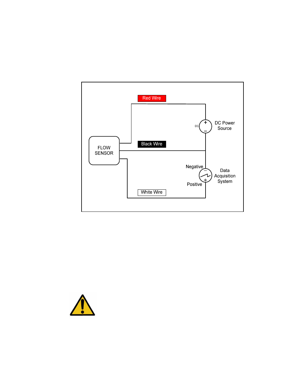
Wiring Schematic For Voltage Output Units.
The RED wire should be connected to the Positive of the power source.
The BLACK wire should be connected to the Negative ( Ground ) of the
power source.
The WHITE wire provides the signal output and should be connected to
the positive terminal of the display, data acquisition system or voltmeter
with an impedance greater than 2500Ω (Ohms).
The GREEN wire is not used.
Caution: Avoid high voltage static discharges to any of the
connections. Do not short the input/output signal wires or allow
them to contact the power wires at any time. DAMAGE WILL
RESULT!