Omega Engineering OS1592 User Manual
Page 8
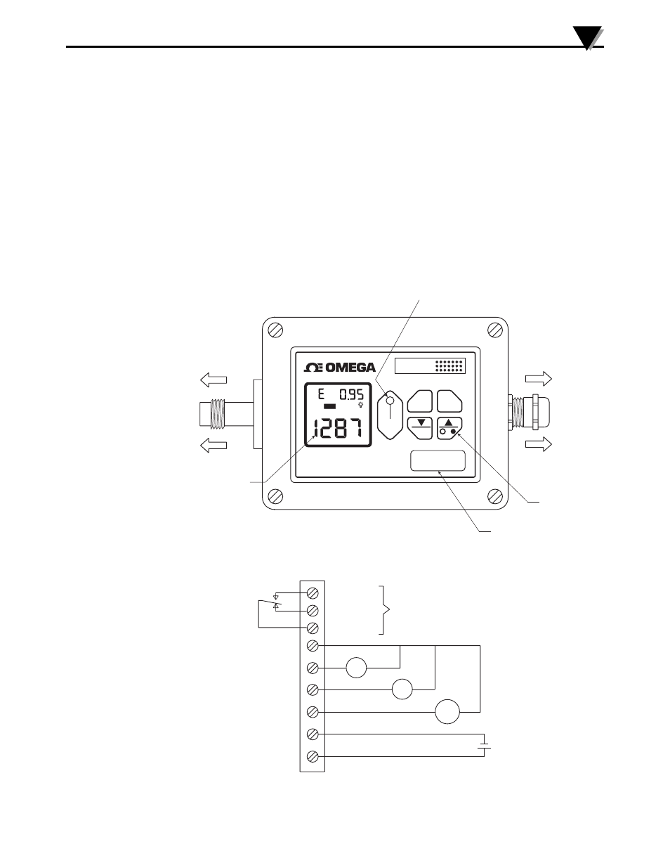
2.2 – Electrical Connection
Attach the optical assembly to the optical adapter located on the side of
the housing. Refer to Fig. 1 for the overall appearance of the unit.
Open the cover of the aluminum housing. Slide your cable through the
metal feed thru and connect the wires to the 9 position terminal block
(J101) as shown in Fig. 2. Depending on the type of the analog outputs,
you need to make the proper connection. Connect the shield of the cable
to the inside of the metal feed thru to minimize RF noise.
In order to use the Backlight source OS1500-BLS, disconnect the fiber
optic assembly from the main electronic unit and connect to the light
source. The focused light through the fiber optic assembly provides the
positioning of the optical assembly on the target. After the positioning,
reconnect the fiber optic assembly back to the main unit.
Figure 1 - OS1592 Main Unit
Figure 2 - Power Supply and Analog Output Connections
OS1592 Infrared Fiber Optic Thermometer/Transmitter
2
3
MODEL & S/N
ALARM LED
INDICATION
CURRENT
TEMPERATURE
4 POSITION
MEMBRANE
KEYPAD
POWER AND OUTPUT
CONNECTIONS
CONNECT TO THE
OPTICAL ASSEMBLY
ALARM
°F
MODE
°F–°C
SET
OS1590 SERIES
®
FIBER OPTIC
THERMOMETER
HAL
RELAY
CONTACTS
RELAY/COM
RELAY/NC
RELAY/NO
ANALOG
OUTPUTS
J & K T/C
0/5VDC, 0/10VDC
4/20mA
V/TC
+
1mV/Deg
mV
+
–
+
mA
POWER
SUPPLY
18-36VDC
+
–
J101
9
1