Appendix 1: model ldp-1xx-cx as slave repeater, Configuration diagram – Omega LDP-124 User Manual
Page 15
JP1
JPA2
T
S
M4
8T02-
200P
C1
1
137A
TIM
EK
EEPER
TM
RAM
LIT
HIU
M
B
A T
TE
RY
MA
LA
YSIA
JPA3
JPA4
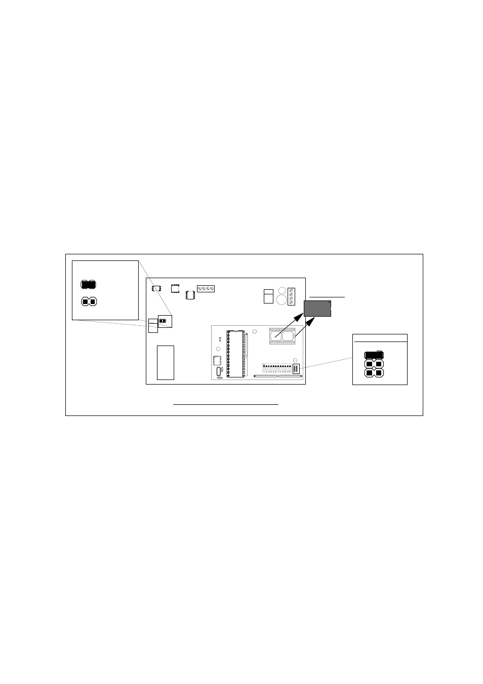
REMOVE IC4
SITUATION JUMPER JPA2
JP1
Configuration Diagram.
Charge
connected
Charge
disconnected
C.I.98/04
C.I.98/06
APPENDIX 1: MODEL LDP-1XX-CX AS SLAVE REPEATER.
FUNCTIONAL DESCRIPTION:
Special configuration of Models LDP-1XX-CX for serial RS-422 repeater, to be used as slaves.
The Serial port connection which is the only that keeps in operation, it is used to enter the data coming
from the Master.
The rest of functions and connections of these Models, remain disabled.
CONFIGURATION OF A SLAVE MODEL, STARTING FROM A MASTER MODEL LDP-1XX-CX:
- Remove the integrated circuit "IC4" placed on the PCB "98/04" and close jumper JPA2.
CONFIGURATION OPTIONS:
Jumper JP1 placed on PCB "98/06", connects the RS-422 line termination (220 Ohm.).
The rest of the Mini-dips and Jumpers are disabled on this Mode.
OPERATION:
After powered up the unit, the 4 digit Models will display "SLU" and the 6 digit Models will display "SLAUE".
These above indications will remain on the Display, until to receive valid data through RS-422 channel.
Page : 14