Pin description (continued) – Oki MSM66P201 User Manual
Page 8
8/30
¡ Semiconductor
MSM66201/66P201/66207/66P207
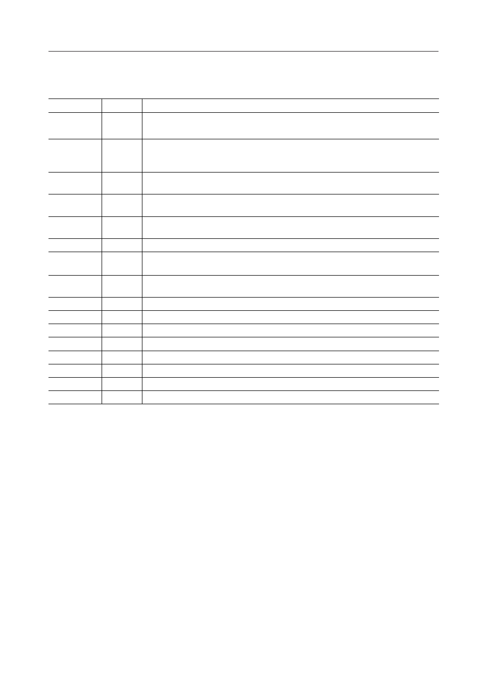
PIN DESCRIPTION (Continued)
RESOUT
Outputs "H" level in the case of internal reset.
Reset to"L" level by program.
ALE
Address Latch Enable:
PSEN
Program Strobe Enable:
RD
Output strobe activated during a bus read cycle.
Used to enable data onto the bus from the external data memory.
WR
Output strobe during a bus write cycle.
Used as write strobe to external data memory.
I
READY
Used when the CPU accesses low-speed peripherals.
EA
Normaly set to "H" level.
If set to "L" level, the CPU fetches the code from external program memory.
FLT
If FLT is "H" level, ALE, WR, RD, PSEN are set to "H" level when reset.
If FLT is set to "L", ALE, WR, RD, PSEN are set to floating level when reset.
RES
RESET input pin.
OSC0
OSC1
Basic clock oscillation pin.
NMI
Non-maskable interrupt input pin (falling edge).
V
REF
Reference voltage input pin for A/D converter.
AGND
Ground for A/D converter.
V
DD
System power supply.
GND
Ground.
Type
Description
Symbol
O
O
O
O
O
I
I
I
I
I
O
—
—
—
—
The timing pulse to latch the lower 8 bits of the address
output from port 0 when the CPU accesses the external
memory.
The strobe pulse to fetch to external program
memory.
Basic clock oscillation pin.