Omega Engineering FSW-50 User Manual
Page 4
2
Available Drag Disks
The FSW-50 Series Switches come with three different drag disks. The
drag disks are sized as follows:
DRAG DISK
SIZE
#1
.5" dia.
#2
.83" dia.
#3
1.0" dia.
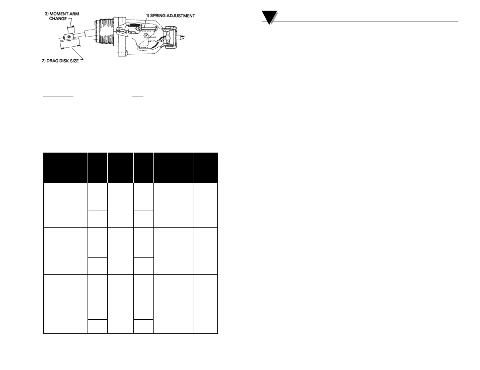
The following table lists flow adjustment limits for various pipe sizes
relative to Model No. and drag disk size. The moment arm (see Step 3 of
FLOW RANGE) is held constant at the maximum value. Decreasing the
moment arm, increases the adjustment range.
Low Flow
Nominal
Pipe
Nominal
High Flow
% Increase
Model
Low Flow
Size
High Flow
Model
of Listed
Number
Cont. Adj.
(Ins.)
Cont. Adj.
Number
Flows via
Range
Range
Moment
(GPM)
(GPM)
Arm Adj.
FSW-50 w/drag
* **
* **
FSW-50 w/drag
disk #2
8-13
1
18-28
disk #1
None
Shortest drag
Shortest drag
disk arm.
disk arm.
Mid. size
3.3-5.3
7.4-11.5
Smallest drag
drag disk
ft/sec
ft/sec
disk
FSW-51 w/drag
15-30
1
1
/
2
30-60
FSW-51 w/drag
disk #3
25-50
2
50-105
disk #1
None
40-80
2
1
/
2
80-155
Mid. size
Mid. size
drag disk
drag disk
arm. Largest
2.7-5.4
5.4-10.8
arm. Smallest
drag disk
ft/sec
ft/sec
drag disk
FSW-52 w/drag
40-90
3
90-180
FSW-52 w/drag
disk #3
60-120
3
1
/
2
120-240
disk #1
+25%
75-155
4
155-310
Longest drag
120-245
5
245-480
Longest drag
disk arm.
180-350
6
350-700
disk arm.
Largest
300-600
8
600-1200
Smallest
drag disk
500-950
10
950-1900
drag disk
2.4-4.0
4.0-8.0
ft/sec
ft/sec
*
*
Force/Balance spring relaxed.
**Force/Balance spring fully extended.
Notes
11