Calibration – Omega Vehicle Security DRA-RTM-8 User Manual
Page 8
6
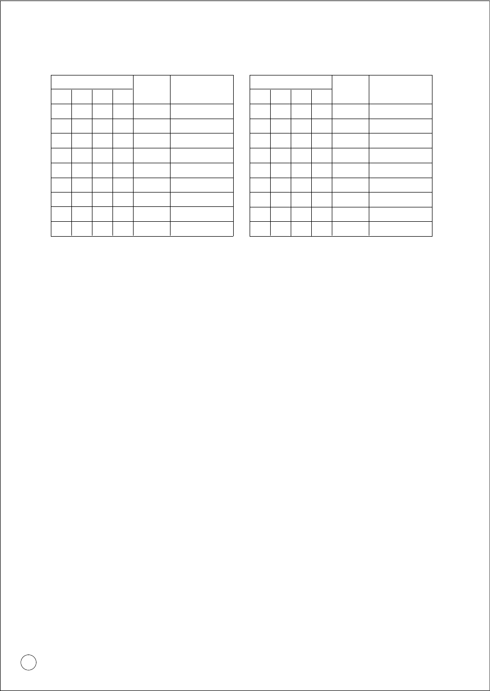
ADDRESS BUS
E/T
OUTPUT
CHANNEL
A0
A1
A2
A3
1
1
1
1
1
0
0
0
0
1
0
0
1
1
0
0
1
0
1
0
1
1
1
1
1
9
10
11
12
13
1
1
1
x
1
1
1
x
0
1
1
x
1
0
1
x
1
1
1
0
14
15
16
TEST MODE
ADDRESS BUS
E/T
OUTPUT
CHANNEL
A0
A1
A2
A3
0
0
0
0
0
0
0
0
0
1
0
0
1
1
0
0
1
0
1
0
1
1
1
1
1
1
2
3
4
5
0
0
0
x
1
1
1
x
0
1
1
x
1
0
1
x
1
1
1
0
6
7
8
TEST MODE
9.4.2 "TRUE HIGH" SETTING
Note: The unit includes three internal potentiometers. These potentiometers
are carefully adjusted and sealed in the factory. It is not recommended
to alter these calibration potentiometers.
10. CALIBRATION
To calibrate the DRA-RTM-8, the limits must be defined.
Tmin is the temperature at which the output current is 4mA.
Tmax is the temperature at which the output current is 20mA.
Tspan is the difference between Tmax and Tmin.
10.1 CALIBRATION PROCEDURE
a. Remove the terminal strips to get access to the coarse calibration switches.
b. Set the channels DIP switches to the desired calibration ranges according to the
calibration tables.
c. Re-install the terminals strips. The terminal strips are polarized and should be
returned to their original position.
d. Connect a Pt-100 calibrator* set for Tmin to the proper input terminals.
e. Apply the proper channel selection code by connecting those which according
the table should be "1" to the +PWR terminal.
f. Start calibrating by adjusting the proper "Z" potentiometer to obtain an output
current of 4.000mA.
g. Set the calibrator for Tmax and adjust the "S" potentiometer to obtain an output
current of 20.000mA.
h. Repeat this procedure until satisfactory results are obtained.