A/d mode control register, 8 a/d mode control register – Omega Engineering OME-A8111 User Manual
Page 18
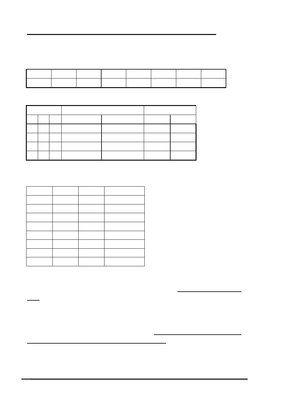
2.4.8 A/D Mode Control Register
(WRITE) Base+B : A/D Mode Control Register Format
Bit 7
Bit 6
Bit 5
Bit 4
Bit 3
Bit 2
Bit 1
Bit 0
X SI2 SI1 SI0 X D2 D1 D0
X=don‘t care
Mode Select
Trigger Type
Transfer Type
D2 D1 D0 Software Trig
Pacer Trig
Software Interrupt
0 0 0
Select
X
Select
X
0 0 1
Select
X
Select
X
0 1 0
X
Select
X
X
1 1 0
X
Select
Select Select
X=disable
SI2 SI1 SI0 IRQ
Level
0 0 0 IRQ2
0 0 1 Not
used
0 1 0 IRQ2
0 1 1 IRQ3
1 0 0 IRQ4
1 0 1 IRQ5
1 1 0 IRQ6
1 1 1 IRQ7
The A/D conversion operation can be divided into 2 stages, trigger stage and transfer
stage. The trigger stage will generate a trigger signal to the A/D converter and the transfer
stage will transfer the results to the CPU.
The trigger method may be an internal trigger or an external trigger. The internal
trigger can be a software trigger or a pacer trigger. The software trigger is very simple
but can not control the sampling rate very precisely. In software trigger mode, the
program issues a software trigger command (sec. 2.4.9) any time needed. Then the program
will poll the A/D status bit until the ready bit is 0 (sec. 2.4.2).
OME-A-8111 Hardware Manual (ver.1.1, Jul/2003) 16