Omega Vehicle Security OMG-USB-DIO48 User Manual
Page 15
Programming
OMG-USB-DIO48
Page 11
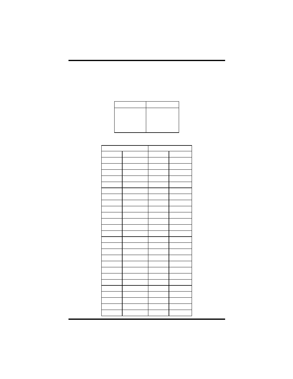
Figures 8 and 9 are provided for the user to record their particular relative
addressing setup, provided its constant. Print this page and fill in the tables
starting in the top left corner of each and work from top to bottom, left to right.
Start with zero (0) on the first input and increment by one on each additional
input. Next move to outputs and again start with zero (0) and increment by one
on each addit ional output.
Bank 1 – P2
Bank 2 – P3
Address Port Address Port
A1
A2
B1
B2
C1
C2
Figure 8- Absolute Bit Address (Same for any configuration)
Bank 1 – P2
Bank 2 – P3
Address
Port-Bit
Address
Port-Bit
A1-0
A2-0
A1-1
A2-1
A1-2
A2-2
A1-3
A2-3
A1-4
A2-4
A1-5
A2-5
A1-6
A2-6
A1-7
A2-7
B1-0
B2-0
B1-1
B2-1
B1-2
B2-2
B1-3
B2-3
B1-4
B2-4
B1-5
B2-5
B1-6
B2-6
B1-7
B2-7
C1-0
C2-0
C1-1
C2-1
C1-2
C2-2
C1-3
C2-3
C1-4
C2-4
C1-5
C2-5
C1-6
C2-6
C1-7
C2-7