C1. parts diagram: omega 200 – Outback Power Systems OMEGA 300 User Manual
Page 5
5
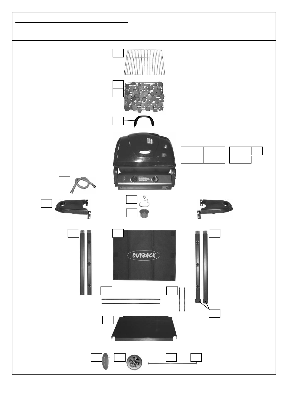
C1. Parts Diagram: Omega 200
Quantities vary according to model purchased. Specifications subject to change without prior notice.
For more details on hardware, please see ‘Hardware Reference Diagram: Omega 200.’
C10
C4
C3
C5
C1
C8
C7
Pre-assembled body unit includes
the following individual parts:
A8
A1
A9
A3
A2 A4 A5 A10
B1 B2
A11 A12 A13 A14
A6
A7
B5 B6
B6
B7
C6
C9
B3
C2
D7