Orion XT10 User Manual
Page 13
13
Aligning the Secondary Mirror
With the collimation cap in place, look through the hole in the
cap at the secondary (diagonal) mirror. Ignore the reflections
for the time being. The secondary mirror itself should be cen-
tered in the focuser drawtube, in the direction parallel to the
length of the telescope. If it isn’t, as in Figure 18b, it must be
adjusted. This adjustment will rarely, if ever need to be done.
Using a 2mm hex key, loosen the three small alignment
set screws in the center hub of the 4-vaned spider several
turns. Now keep the mirror’s holder stationary (be careful not
to touch the surface of the mirrors), while turning the cen-
ter screw with a Phillips head screwdriver (See Figure 20).
Turning the screw clockwise will move the secondary mirror
toward the front opening of the optical tube, while turning
the screw counter-clockwise will move the secondary mirror
toward the primary mirror.
Note: When making these adjustments, be careful not to
stress the spider vanes or they may bend.
When the secondary mirror is centered in the focuser draw-
tube, rotate the secondary mirror holder until the reflection of
the primary mirror is as centered in the secondary mirror as
possible. It may not be perfectly centered, but that is OK. Now
tighten the three small alignment screws equally to secure
the secondary mirror in that position.
If the entire primary mirror reflection is not visible in the sec-
ondary mirror, as in Figure 18c, you will need to adjust the tilt
of the secondary mirror. This is done by alternately loosen-
ing one of the three alignment hex screws while tightening
the other two, as depicted in Figure 21. Do not make exces-
sive turns of these hex screws or force them past their normal
travel. A simple 1/2 turn of the screw can dramatically change
the tilt of the mirror. The goal is to center the primary mir-
ror reflection in the secondary mirror, as in Figure 18d. Don’t
worry that the reflection of the secondary mirror (the smallest
circle, with the collimation cap “dot” in the center) is off-center.
You will fix that in the next step.
Adjusting the Primary Mirror
The final adjustment is made to the primary mirror. It will need
adjustment if, as in Figure 18d, the secondary mirror is cen-
tered under the focuser and the reflection of the primary mirror
is centered in the secondary mirror, but the small reflection of
the secondary mirror (with the “dot” of the collimation cap) is
off-center.
The tilt of the primary mirror is adjusted with three spring-
loaded collimation thumbscrews on the back end of the
optical tube (bottom of the primary mirror cell); these are the
larger thumbscrews. The three smaller thumbscrews lock the
mirror’s position in place. These thumbscrews must be loos-
ened before any collimation adjustments can be made to the
primary mirror.
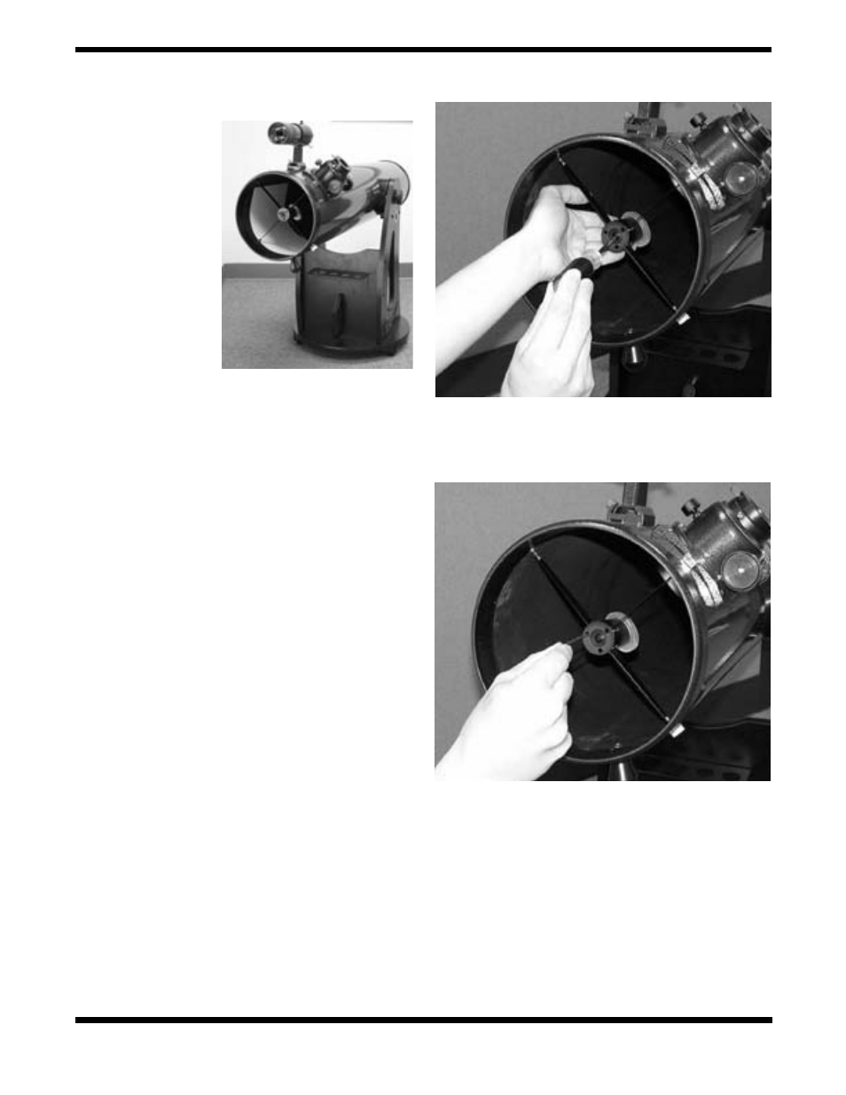
Figure 19.
The SkyQuest
IntelliScope properly set up
for collimation. Note the
white paper placed across
from the focuser, and the
level angle of the optical
tube. Ideally, the telescope
should be pointing at a
white wall.
Figure 20.
To center the secondary mirror under the focuser, hold
the mirror holder in place with one hand while adjusting the center
bolt with a Phillips screwdriver. Do not touch the mirror’s surface!
Figure 21.
Adjust the tilt of the secondary mirror by loosening or
tightening the three alignment set screws with a 2mm hex key.