Warning – Roberts Gorden UHD[X][S][R] 150 User Manual
Page 14
UHD S
TANDARD
D
UCT
F
URNACE
I
NSTALLATION
O
PERATION
AND
S
ERVICE
M
ANUAL
8
5.1.3 Air Flow And Temperature Rise Ranges
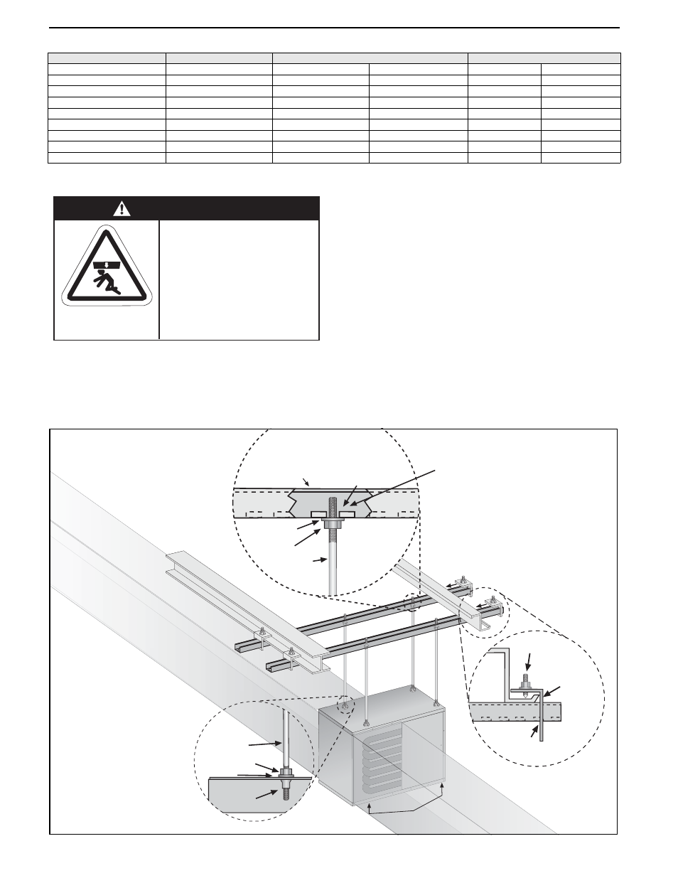
5.2 Suspension
Four suspension points (3/8" nuts) are located on
the top of the heater. Drop rods must be 3/8"
diameter mild steel.
When handling or supporting the heater from below,
ensure that the weight is taken at the support points.
For typical suspension, See Page 8, Figure 3.
The gas or electrical supply lines must not be used
to support the heater.
Do not locate the gas or electrical supply lines
directly over the path of the flue products from the
heater.
The heater must be installed in a location that is
readily accesible for servicing.
The heater must be installed in accordance with
clearances to combustibles as indicated on the wall
tag and in this manual.
Figure 3: Suspension Methods
Model
Rate
Air Flow
Temperature Rise
(Btu/h)
Minimum (CFM)
Maximum (CFM)
Minimum (°F)
Maximum (°F)
UHD[X][S][R] 150
150,000
1,360
5,800
20
83
UHD[X][S][R] 175
175,000
1,400
6,850
20
95
UHD[X][S][R] 200
200,000
2,050
7,750
20
73
UHD[X][S][R] 225
225,000
2,100
8,300
20
80
UHD[X][S][R] 250
250,000
2,350
8,850
22
80
UHD[X][S][R] 300
300,000
2,700
10,200
23
86
UHD[X][S][R] 350
350,000
3,120
13,600
22
86
UHD[X][S][R] 400
385,000
3,420
14,200
22
86
WARNING
Crush Hazard
Use 3/8" threaded rod
minimum.
Failure to follow these
instructions can result in
death, injury or property
damage.
Nut
Washer
Riv
Nut
Ensure all suspension
hardware is torqued to
a minimum of 20 ft lbs.
Support Points
3/8"
Threaded
Rod
Cone Point
Set Pin
Window
Clamp
Unistrut
Unistrut
3/8"
Threaded
Rod
Washer
Nut
Channel Nut
NOTE: Duct
supports
not
shown.
Duct supports
and
duct are
not
provided by
manufacturer.