3 ctua wiring diagram (models 22-60), Section 10.3, Ignition module – Roberts Gorden COMBAT CTU 22 TO 115 User Manual
Page 22: Site wiring
COMBAT
®
CTU U
NIT
H
EATERS
I
NSTALLATION
O
PERATION
AND
S
ERVICE
M
ANUAL
16
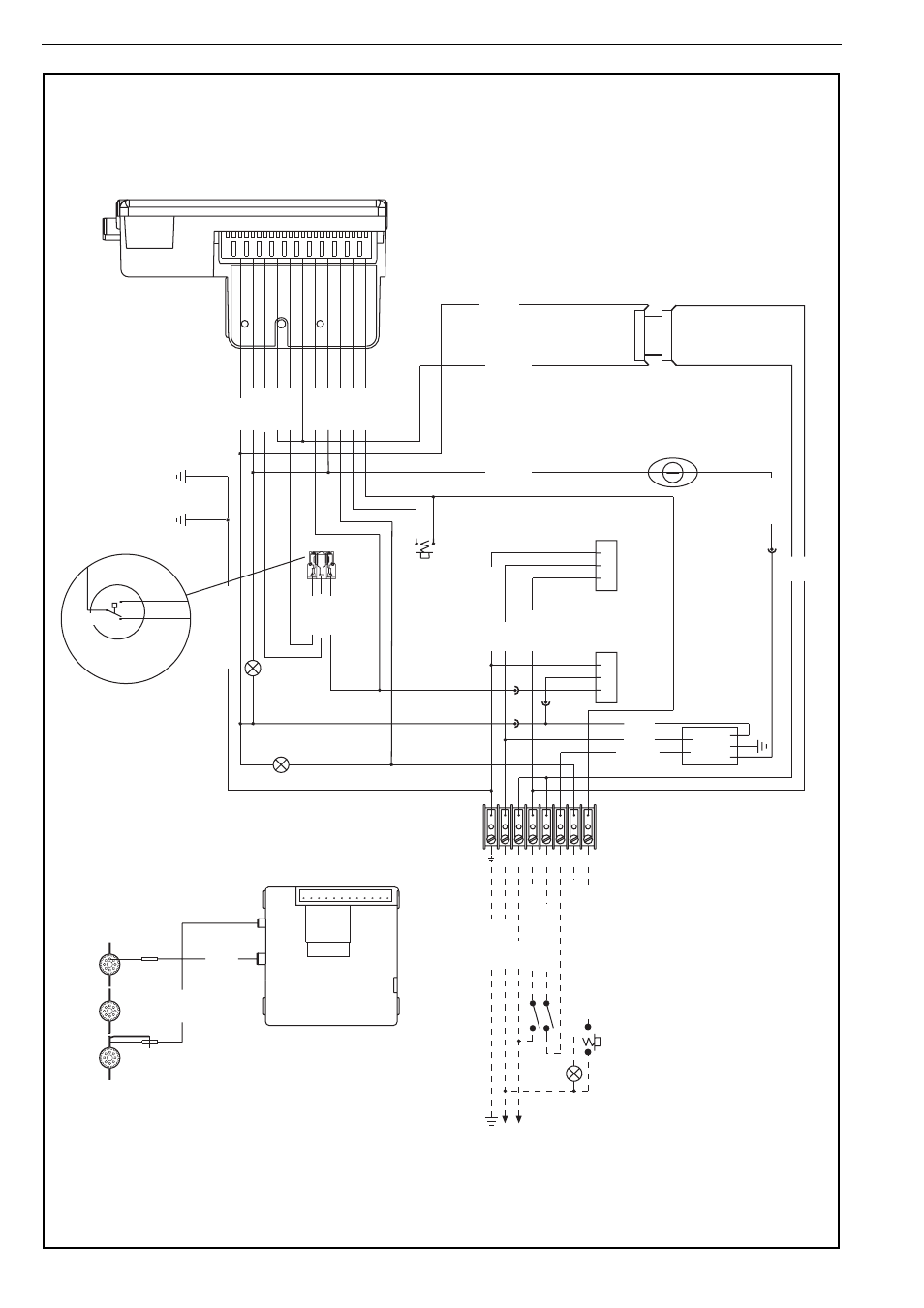
10.3 CTUA Wiring Diagram (Models 22-60)
IGNITION MODULE
BLACK
Plug in Connection to Gas Valve
S4565C 1017 Control
Honeywell
BLACK
SENSE
IGNITION
230 V
1 Ø
50 Hz
IGNITION MODULE
LOCKOUT
GAS VALVE
RUN
11
12
7
9
10
8
5
6
4
SITE WIRING
2
3
1
E
N L 1 2 3 7 8
BLUE
BROWN
BLUE
MAINS FILTER
Pressure Switch
Detail
WHITE
YELLOW
BLACK
Thermostat Limit
Thermodisc N/C
BROWN
BROWN
RED
RED
AXIAL
F
AN
COMBUSTION
FA
N
N
L
E
N
L
REMOTE LOCKOUT
RESET
REMOTE LOCKOUT
INDICA
TION
THERMOST
AT
REMOTE F
AN ON
LINE
NEUTRAL
GROUND
YELLOW BLACK
WHITE
PRESSURE SWITCH
GREEN/YELLOW
BLACK BROWN
BROWN
BROWN
YELLOW
BLUE
WHITE
PINK PURPLE
GREY
NO\P(3)
C\P(1)
NC\P(2)
GREEN/YELLOW
BLUE
BROWN
BLUE
BROWN
Time Delay Relay
LOCKOUT
RESET
NOTE:
If any of the original wire supplied with
the heater must be replaced, it must be
replaced with wiring material having a
temperature rating of at least 105° C
and 600 volts.