Electrical – Ryobi AP1301 User Manual
Page 8
8
9
SPEED AND WIRING
The no-load speed of this tool is approximately 10,000 rpm.
This speed is not constant and decreases under a load or
with lower voltage. For voltage, the wiring in a shop is
as important as the motor’s horsepower rating. A line in-
tended only for lights cannot properly carry a power tool
motor. Wire that is heavy enough for a short distance
will be too light for a greater distance. A line that can
support one power tool may not be able to support two
or three tools.
GROUNDING INSTRUCTIONS
In the event of a malfunction or breakdown, grounding
provides a path of least resistance for electric current to
reduce the risk of electric shock. This tool is equipped with
an electric cord having an equipment-grounding conduc-
tor and a grounding plug. The plug must be plugged into a
matching outlet that is properly installed and grounded in
accordance with all local codes and ordinances.
Do not modify the plug provided. If it will not fit the outlet,
have the proper outlet installed by a qualified electrician.
Improper connection of the equipment-grounding conductor
can result in a risk of electric shock. The conductor with
insulation having an outer surface that is green with or with-
out yellow stripes is the equipment-grounding conductor. If
repair or replacement of the electric cord or plug is neces-
sary, do not connect the equipment-grounding conductor
to a live terminal.
Check with a qualified electrician or service personnel if the
grounding instructions are not completely understood, or if
in doubt as to whether the tool is properly grounded.
Repair or replace a damaged or worn cord immediately.
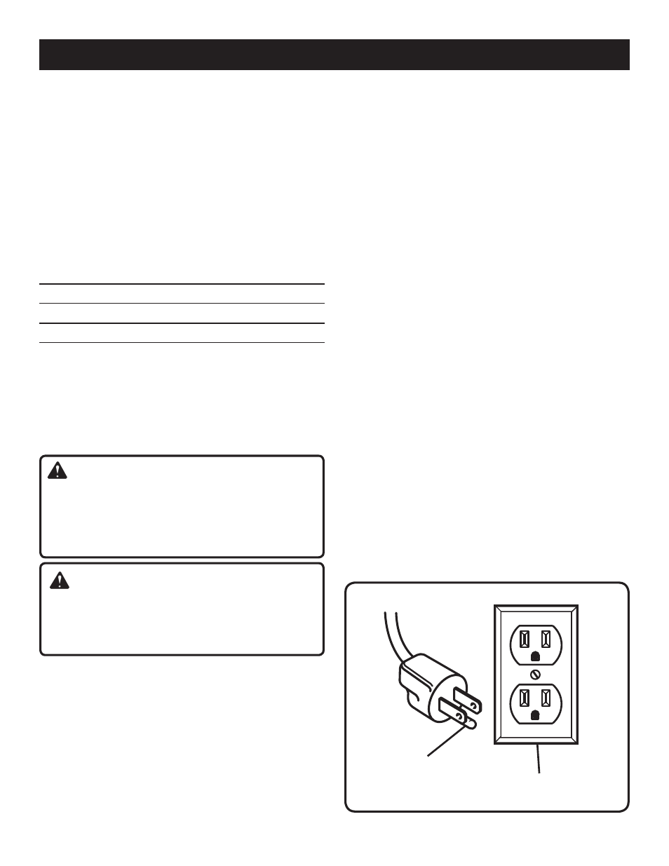
This tool is intended for use on a circuit that has an outlet
like the one shown in figure 1. It also has a grounding pin
like the one shown.
ELECTRICAL
Fig. 1
GROUNDING
PIN
COVER OF GROUNDED
OUTLET BOX
EXTENSION CORDS
Use only 3-wire extension cords that have 3-prong ground-
ing plugs and 3-pole receptacles that accept the tool’s plug.
When using a power tool at a considerable distance from the
power source, use an extension cord heavy enough to carry
the current that the tool will draw. An undersized extension
cord will cause a drop in line voltage, resulting in a loss of
power and causing the motor to overheat. Use the chart
provided below to determine the minimum wire size required
in an extension cord. Only round jacketed cords listed by
Underwriter’s Laboratories (UL) should be used.
**Ampere rating (on tool faceplate)
0-2.0 2.1-3.4 3.5-5.0 5.1-7.0 7.1-12.0 12.1-16.0
Cord Length Wire Size (A.W.G.)
25' 16 16 16 16 14 14
50' 16 16 16 14 14 12
100' 16 16 14 12 10 —
**Used on 12 gauge - 20 amp circuit.
NOTE: AWG = American Wire Gauge
When working with the tool outdoors, use an extension cord
that is designed for outside use. This is indicated by the let-
ters “WA” on the cord’s jacket.
Before using an extension cord, inspect it for loose or
exposed wires and cut or worn insulation.
WARNING:
Keep the extension cord clear of the working area.
Position the cord so that it will not get caught on lumber,
tools or other obstructions while you are working with a
power tool. Failure to do so can result in serious personal
injury.
WARNING:
Check extension cords before each use. If damaged re-
place immediately. Never use tool with a damaged cord
since touching the damaged area could cause electrical
shock resulting in serious injury.
ELECTRICAL CONNECTION
This tool is powered by a precision built electric motor. It
should be connected to a
power supply that is 120 volts,
60 Hz, AC only (normal household current). Do not operate
this tool on direct current (DC). A substantial voltage drop
will cause a loss of power and the motor will overheat. If the
tool does not operate when plugged into an outlet, double
check the power supply.