Connecting – Roland VC-200HD User Manual
Page 14
14
Connecting
Connect the VC-200HD or VC-300HD in the way that is appropriate for the intended purpose.
This section describes how the various connections need to be made, according to purpose.
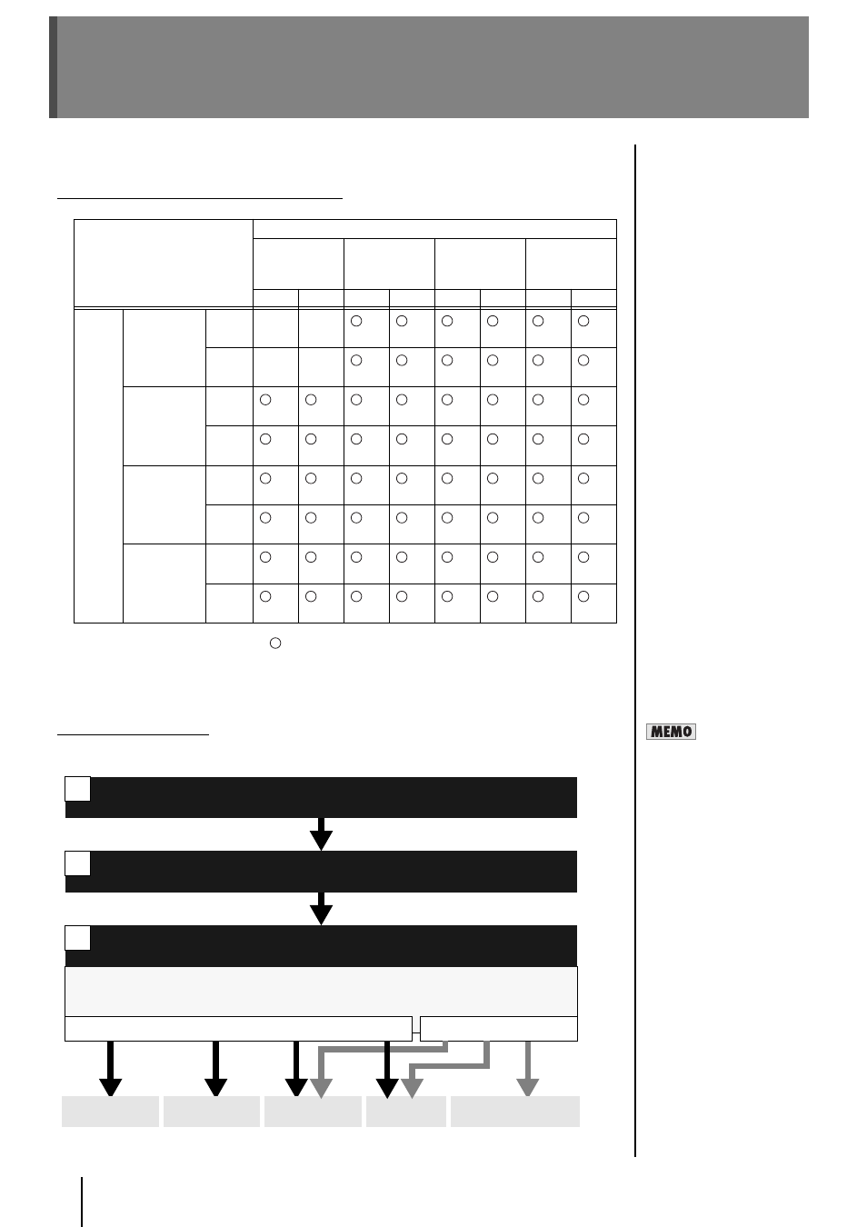
Connection Overview and Support Pages
* The combinations indicated with
in the chart are input/output that can be converted.
* The input/output combinations are described on the pages indicated in the chart with p. ??.
* Wherever “VC-300HD” appears, it means that it is supported only on the VC-300HD.
* Wherever “—” is shown, it means that it is not supported on either the VC-200HD or VC-300HD.
About the Procedures
In general, the operating procedures introduced in p. 15–25 involve proceeding through the steps
below.
Input
i.LINK
Connector
COMPONENT
INPUT
Connector
DVI-I
Connector
HD-SDI IN
Connector
HDV
DV
HD
SD
Digital
Analog HD
SD
Output
i.LINK
Connector
HDV
—
—
DV
—
—
COMPONEN
T OUTPUT
Connector
HD
SD
DVI-I
Connector
Digital
Analog
HD-SDI OUT
Connector
HD
SD
Frame Rate
This index indicates the
number of times (number of
frames) that a screen can be
redrawn per second.
For example, a value of 1080/
59.94i means that the screen
is redrawn 59.94 times per
second.
Connect the devices
Output of the audio/video in the selected format begins from the appropriate output connectors.
Process for up-conversion, down-conversion, and frame rate conversion are automatically set with
the settings for step 2 and step 3.
Video Output
Audio Output
Select the input connectors (video/audio)
See “Selecting the video input connector” (p. 26), “Selecting the audio input connector” (p. 27).
Select the output format (video only)
See “Selecting the video output format” (p. 27).
1
2
3
COMPONENT
OUTPUT
HD-SDI
OUT
DVI-I
OUTPUT
i.LINK
OUTPUT
AUDIO OUTPUT
CH1/2, CH3/4