Rhino Mounts NITRO FN10 User Manual
Fn10/fn15 nitro, Operator’s manual
©2010 Alamo Group Inc.
FN10/FN15
NITRO
Published 02/10
Part NO. 00779794C
OPERATOR’S MANUAL
RHINO
®
1020 S. Sangamon Ave.
Gibson City, IL 60936
800-446-5158
Email: [email protected]
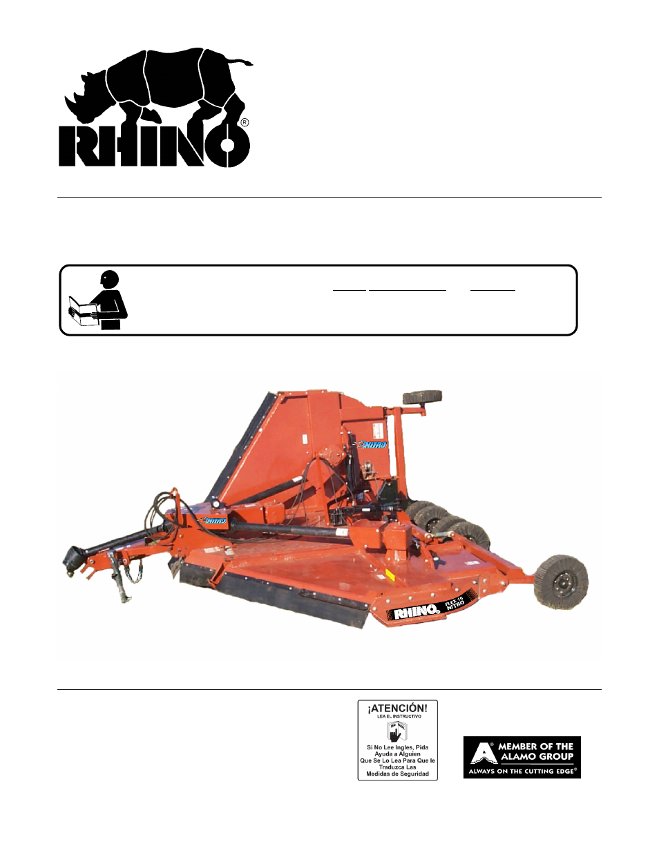
HEAVY-DUTY FLEX-WING
ROTARY CUTTER
This Operator's Manual is an integral part of the safe operation of this machine and must
be maintained with the unit at all times. READ, UNDERSTAND, and FOLLOW the Safety
and Operation Instructions contained in this manual before operating the equipment. C01-
Cover
$0.00
Table of contents
Document Outline
- FN10/FN15
- NITRO
- OPERATOR’S MANUAL
- To the Owner/Operator/Dealer
- Alamo Group Ag. Division is willing to provide
- one (1) AEM Mower Safety Practices Video
- TABLE OF CONTENTS
- General Safety Instructions and Practices
- Operator Safety Instructions and Practices
- Equipment Operation Safety Instructions and Practices
- Connecting or Disconnecting Implement Safety Instructions and Practices
- Transporting Safety Instructions and Practices
- Maintenance and Service Safety Instructions and Practices
- Storage and Parking Safety Instructions and Practices
- Concluding Safety Instructions and Practices
- Decal Location
- SAFETY SECTION
- 1. D389 1 DECAL Lift Unit Decal Sheet
- 2. D388 1 DECAL Driveline Hazards
- 3. D390 1 DECAL Pull Type Units
- 4. D417 3(2) IMPORTANT Replace Blades in Pairs
- 5. 00753840 2(1) DANGER Folding Wing Thrown Objects
- 6. D401 1 INSTRUCT 1000 RPM (Not Shown)
- 7. 999403 0(1) DANGER Overturn of Two Section Flex
- 8. 00760657 1 IMPORTANT Genuine Parts
- 9. 00756004 4(3) DANGER Shield Missing
- 10. [2] MODEL NAME FL15
- 11. D558 2 LOGO NAME Small Nitro
- 12. D557 2 LOGO NAME Large Nitro
- 13. nfs 1 SER PLATE Serial Number Plate
- 14. D137 2 INSTRUCT CCW Blade Rotation
- 15. D138 1(0) INSTRUCT CW Blade Rotation
- 16. 00771283 1 INSTRUCT 5 Yr. Gearbox Warranty
- 17. 00771284 1 INSTRUCT 2 Yr. Driveline Warranty
- 18. 99102 2(1) NAME Rhino 11-5/8 x 3-1/4
- 19. D302 2 LOGO Rhino 4-7/8 x 6-1/2
- 20. D303 2 LOGO NAME Rhino Type 4-3/8 x 16-3/4
- 21. 03200347 1 REFLECT SMV
- 22. 1458392 2 REFLECT Red Reflector
- 23. 1458393 1 REFLECT Amber Reflector
- 24. 00776031 1 Canister, Operator’s Manual
- 25. 00779794C 1 Operator’s Manual
- 26. 10058000 3 Bolt
- 27. 00024100 6 Flatwasher
- 28. 02959924 3 Locknut
- 29. 1006348 6** WARNING Explosion Hazard
- 30. D482 1 WARNING Jack Positioning
- 31. D520 1 IMPORTANT Transport Latch
- 32. D519 2 DANGER Crushing Hazard - Falling
- 33. D539 (2) 1 DANGER Crushing Hazard - Lock
- Decal Description
- Federal Laws and Regulations
- Attention Owner/Operator
- INTRODUCTION SECTION
- ASSEMBLY SECTION
- DEALER SET-UP INSTRUCTIONS
- ASSEMBLY
- 1. Use the implement jack to raise the implement tongue until it is even with the tractor drawbar. Insert the jack into the jack adapter in the implement tongue and swivel it so that it is vertical. Follow the instructions on the jack. Install the ja...
- 2. Make sure the tractor PTO is the correct speed and shaft size for the implement. Ensure the drawbar is extended the proper distance from the Tractor PTO shaft for desired PTO speed; 540 PTO is 14” and for 1000 PTO speed the distance is 16”
- 3. Carefully back tractor to mower. Do not allow coworkers or bystanders between the tractor and the implement while backing. When dismounting the tractor ALWAYS shut down the tractor, disengage the PTO, and set the parking brake before dismounting.
- 4. Install the retaining bolt through tongue clevis and tractor drawbar. The implement tongue is very heavy. Make any height adjustments using the implement jack. Place two 1” flatwashers (1) positioned under top lip of tongue clevis and to the top...
- 5. Install the implement tow chain to a secure location on the tractor.
- 6. Attach proper hydraulic couplers to implement hose ends. Insert the wing hose quick disconnect couplers into tractor hydraulic remotes.
- 7. Mount tractor, fasten your seatbelt and start engine. From the operators seat use the tractor hydraulic control levers to fill wing cylinders with oil. Filling the cylinders should retract the wings slightly to their minimum closed width. Continue...
- 8. Remove retaining bracket from end yoke of main driveline. Remove main driveline from mower and place on ground or hard surface. Figure AsmP-R-0120
- 9. Make sure the wing Transport Bars/Latches are locked in the position to hold the wings vertical before removing shipping strap. Figure AsmP- R-0118
- 10. Stand between the wings of the implement and remove nuts holding the shipping strap in place and remove strap.
- 11. Filling the cylinders with oil should raise the wings slightly and loosen the wing Transport Bars/Latches retaining pin. NOTE: DO NOT release the wing Transport Bar/Latch if there is a force on the pin. If there is a force holding the Transport B...
- 12. From the tractor seat use the tractor hydraulic control levers to lower the wing(s).
- 13. Continue to hold the control lever until both wings are down and the wing cylinders are fully extended. Continue to cycle the cylinders several times by raising and lowering the wings fully to remove any trapped air. If there is sponginess during...
- 14. Test to make sure the wings lower slowly when they are allowed to float down and are not powered down. This is a safety feature built into the system. If the wings fall rapidly, have the hydraulic system or cylinders repaired before operating the...
- CONNECTING DRIVELINE
- DRIVELINE ATTACHMENT
- 1. Remove double clamp bolts from main driveline implement connection yoke and insert onto power divider gearbox shaft. Insert clamp bolt and tighten to 170 ft. lbs.
- 2. Inner center axle dual tire assemblies are shipped bolted on wing mount tubes. Remove transport bars from wings and lower each wing so that inner tire and hub assembly can be removed and installed on center axle. NOTE: It will be necessary to rais...
- 3. Install gearbox vents or vent dipsticks if not installed.Check all gearbox lube levels.
- TIRES AND WHEELS
- RHINO FN10/FN15 NITRO ROTARY MOWER
- OPERATION INSTRUCTIONS
- 1. Standard Equipment and Specifications
- 3. TRACTOR REQUIREMENTS
- Tractor Requirements and Capabilities
- 3.1 ROPS and Seat Belt
- 3.2 Tractor Safety Devices
- 3.3 Tractor Horsepower
- 3.4 Drawbar
- 3.5 Tractor Hydraulics
- 3.6 Front End Weight
- 3.7 Power Take Off (PTO)
- 3.8 Tire Spacing
- 4. GETTING ON AND OFF THE TRACTOR
- 5. STARTING THE TRACTOR
- 6. CONNECTING THE MOWER TO THE TRACTOR
- 6.1 Connecting the Mower Tongue to the Tractor
- 1. Ensure the tractor is equipped with the correct PTO shaft and the drawbar is set at the correct length.
- 2. Using the parking jack, position the tongue clevis to the height of the tractor drawbar. Adjust the mower tongue to be level and parallel with the tractor drawbar using the control rod connecting the mower tongue to the deck.
- 3. Board the tractor and start the engine. Back the tractor to the mower aligning the drawbar hitch hole with the mower tongue clevis. Turn off the tractor engine, place the tractor in park, and set the parking brake before dismounting.
- 4. To attach the mower, place two 1” flatwashers positioned under top lip of tongue clevis and to the top of drawbar. Insert a 1” diameter grade 5 or 8 bolt through clevis and drawbar and retain in position with a 1” locknut. Tighten the locknu...
- 5. Securely attach the mower safety chain to the tractor drawbar or drawbar support frame.
- 6. Lower the jack until the tongue is completely supported by the drawbar. Remove jack from the tongue and place on storage bracket of mower.
- 6.2 Connecting Mower Hydraulic Lines to the Tractor
- 6.1 Connecting the Mower Tongue to the Tractor
- 7. SETTING THE MOWER
- 7.1 Setting Deck Height
- 1. Place the tractor and mower on a level surface and lower both wings.
- 2. Using the center section hydraulic cylinder, position the mower so the skid shoes are 1” less off the ground than the desired final cut height. For example, for a 3” cut raise or lower the mower until the skid shoes are approximately 2” off ...
- 3. Shut down the tractor, place the transmission in park, and set the parking brake before dismounting.
- 4. Level the mower deck front to rear by adjusting the leveling rods linking the tongue to the rear axle. DO NOT allow feet or other body part underneath the mower when making adjustments. To adjust rod length, loosen jamnut and screw turnbuckles. To...
- 5. IMPORTANT: Alternate adjustments between rods and adjust at equal lengths to maintain equal tension. Improper adjustments may cause rods to snap or bend.
- 6. Place split collar assemblies on the center axle hydraulic cylinder rod to maintain a set cutting height each time the mower is raised and lowered.
- 7.2 Setting Deck Pitch
- 7.1 Setting Deck Height
- 8. DRIVELINE ATTACHMENT
- 9. PRE-OPERATION INSPECTION AND SERVICE
- 10. DRIVING THE TRACTOR AND IMPLEMENT
- 11. OPERATING THE TRACTOR AND IMPLEMENT
- 12. DISCONNECTING THE MOWER FROM THE TRACTOR
- 13. MOWER STORAGE
- 14. TRANSPORTING THE TRACTOR AND IMPLEMENT
- 15. TROUBLESHOOTING GUIDE
- Lubrication
- CENTER & WING GEARBOXES
- GEARBOX ARRANGEMENTS (Secondary Gearboxes)
- MAIN CV DRIVELINE SHIELD SERVICE INSTRUCTIONS
- 1. Clean and grease bushing groove before the bushing is placed in the groove. Grease any remaining bushings in guard.
- 2. Slide guard half over driveline and insert bushing tabs into the openings in the guard.
- 3. Turn the bushing until it engages into the guard.
- 4. Push Easy Lock clip into position. The bushing and guard are now secure.
- 5. TO REMOVE GUARD - Use screwdriver to release Easy Lock clip. Turn the bushing to disengage from the guard and remove guard. Figure Mnt-R-0359
- BLADE SERVICING
- BLADE SHARPENING
- BLADE CARRIER REMOVAL
- BLADE CARRIER INSPECTION
- BLADE CARRIER INSTALLATION
- TORQUE LIMITER
- f. With the three Capscrews (#8) backed out until the points are below the surface of the circular Adjusting Nut (#7), run Adjusting Nut up finger-tight, or slightly less than finger-tight.
- g. Alternately tighten the hardened, cup point Capscrews (#8) no more than one-half turn at a time until the Capscrew heads "Bottom Out". Do not over tighten the Capscrews nor completely flatten the Spring Washers (#5).
- SEASONAL CLUTCH MAINTENANCE
- 1. Loosen Bolts (#8) until gap between adjusting nut (#7) and guide ring is approximately 1/16".
- 2. Attach machine to tractor, set engine at approximately half throttle and quickly engage PTO. This procedure will break clutch facings loose and allow the proper torque to be maintained.
- 3. Return the bolts to their original position as described in (b) above.
- SLIP CLUTCH REPAIR PROCEDURE
- 1. Remove two bolts from top cover plate which holds shield bracket to gearbox.
- 2. Remove locknuts #11 from bolts #12.
- 3. Remove cotter pin #13, castle nut #14, and washer #15. NOTE: It may be necessary to rotate yoke to remove cotter pin. Remove driveline yoke from shaft.
- 4. Loosen three bolts #8 until large nut #7 maybe removed from hub #1.
- 5. Remove all parts from hub #1.
- 6. Clean or sand outer plates #2 and center plate #4 to remove rust or burned lining material from plates.
- 7. Reassemble clutch as shown in Figure 22 replacing parts as necessary.
- 8. Install driveline yoke onto shaft and install four bolts through yoke spacer #10 and center plate #4. Install locknuts and tighten.
- 9. Rotate yoke and center plate so that cotter pin #13 can be installed.
- 10. Tighten large nut #7 as much as possible by hand. NOTE: Make sure both springs #5 are centered on guide ring #6.
- 11. Tighten three bolts #8 as far as possible. Clutch setting is automatically set by this procedure.
- 12. Reinstall washer #15 and castle nut #14. CAUTION: Do not ever tighten nut #14. Tighten only enough to remove play between the yoke, washer #15 and nut #14. Install cotter pin.
- WHEEL HUB ASSEMBLY
- TIRES AND WHEELS
- Tongue
- HIGH PRESSURE OIL LEAK HAZARD
- Flex Wing Hydraulic Cylinder Replacement Instructions
- 1. Clear the area of all personnel before lowering the wings.
- 2. From the tractor seat with your seat belt fastened around you, Lower the implement wings to the ground. Do Not attempt to replace the cylinder with the wings in the raised position.
- 3. Shut off the tractor, engage the parking brake, place the tractor transmission in the park position, and remove the key before dismounting.
- 4. Block up the center and wing sections with blocks or jack stands
- 5. Release all oil pressure from the circuit by moving the valve controls handles back and forward.
- 6. Remove the Implement Input Driveline from the tractor PTO shaft.
- 7. Remove the hydraulic hoses from tractor quick disconnects.
- 8. Wear Safety Glass and impenetrable gloves when working with hydraulic hoses and fittings.
- 9. Check to see that the cylinder is not under pressure by moving the cylinder pins by hand. The pins should be loose. If the cylinder pins are in a bind and can not be moved the cylinder maybe under pressure. Make sure the implement decks and axles ...
- 10. Slowly loosen the hydraulic hose connection to the cylinder.
- 11. Remove the other cylinder pin and remove the cylinder. The cylinder maybe heavy, use proper lifting techniques to lift and handle the cylinder and if needed get assistance in lifting from another person.
- 12. Measure the distance between the cylinder pin holes and extend the new cylinder to that length before installing.
- 13. Install the new cylinder in place and install both cylinder pins and retaining clips in place.
- 14. Reconnect hydraulic hose(s) to the cylinder, and tighten the fittings.
- 15. Reconnect the implement hoses to the tractor.
- 16. Get into the Tractor seat and fasten your seat belt. Clear the area of all persons before attempting to raise the wing. From the tractor seat, start the tractor and operate the control valve to raise the wing.
- 17. Look for sign of oil leak. If an oil leak exists, shut the tractor down and remove all oil pressure in the lines by moving the valve control handles back and forward.
- 18. If there are no leaks raise and lower the wing completely at least three full cycles to remove any air trapped in the circuit.
- 19. Check the hydraulic reservoir of the tractor to ensure there is sufficient oil.
- 20. If the wing is to remain in the raised position attached the wing transport latch.
- STORAGE
- 1. Thoroughly clean the cutter.
- 2. Lubricate the cutter as covered in Maintenance Section.
- 3. Tighten all bolts and pins to the recommended torque.
- 4. Check the cutter for worn or damaged parts. Make replacements immediately.
- 5. Store the cutter in a clean, dry place with the cutter housing resting on blocks.
- 6. Use spray touch-up enamel where necessary to prevent rust and maintain the appearance of the cutter.
- PROPER TORQUE FOR FASTENERS
- RHINO
- LIMITED WARRANTY
- 1. LIMITED WARRANTIES
- 1.01. Servis-Rhino warrants for one year from the purchase date to the original non-commercial, governmental, or municipal purchaser (“Purchaser”) and warrants for six months to the original commercial or industrial purchaser (“Purchaser”) th...
- 1.02. Manufacturer will replace for the Purchaser any part or parts found, upon examination at one of its factories, to be defective under normal use and service due to defects in material or workmanship.
- 1.03. This limited warranty does not apply to any part of the goods which has been subjected to improper or abnormal use, negligence, alteration, modification, or accident, damaged due to lack of maintenance or use of wrong fuel, oil, or lubricants, ...
- 1.04. Except as provided herein, no employee, agent, Dealer, or other person is authorized to give any warranties of any nature on behalf of Manufacturer.
- 2. REMEDIES AND PROCEDURES.
- 2.01. This limited warranty is not effective unless the Purchaser returns the Registration and Warranty Form to Manufacturer within 30 days of purchase.
- 2.02. Purchaser claims must be made in writing to the Authorized Dealer (“Dealer”) from whom Purchaser purchased the goods or an approved Authorized Dealer (“Dealer”) within 30 days after Purchaser learns of the facts on which the claim is based
- 2.03. Purchaser is responsible for returning the goods in question to the Dealer.
- 2.04. If after examining the goods and/or parts in question, Manufacturer finds them to be defective under normal use and service due to defects in material or workmanship, Manufacturer will:
- (a) Repair or replace the defective goods or part(s) or
- (b) Reimburse Purchaser for the cost of the part(s) and reasonable labor charges (as determined by Manufacturer) if Purchaser paid for the repair and/or replacement prior to the final determination of applicability of the warranty by Manufacturer.
- 2.05. Purchaser is responsible for any labor charges exceeding a reasonable amount as determined by Manufacturer and for returning the goods to the Dealer, whether or not the claim is approved. Purchaser is responsible for the transportation cost for...
- 3. LIMITATION OF LIABILITY.
- 3.01. MANUFACTURER DISCLAIMS ANY EXPRESS (EXCEPT AS SET FORTH HEREIN) AND IMPLIED WARRANTIES WITH RESPECT TO THE GOODS INCLUDING, BUT NOT LIMITED TO, MERCHANTABILITY AND FITNESS FOR A PARTICULAR PURPOSE.
- 3.02. MANUFACTURER MAKES NO WARRANTY AS TO THE DESIGN, CAPABILITY, CAPACITY, OR SUITABILITY FOR USE OF THE GOODS.
- 3.03. EXCEPT AS PROVIDED HEREIN, MANUFACTURER SHALL HAVE NO LIABILITY OR RESPONSIBILITY TO PURCHASER OR ANY OTHER PERSON OR ENTITY WITH RESPECT TO ANY LIABILITY, LOSS, OR DAMAGE CAUSED OR ALLEGED TO BE CAUSED DIRECTLY OR INDIRECTLY BY THE GOODS INCLU...
- 3.04. NO ACTION ARISING OUT OF ANY CLAIMED BREACH OF THIS WARRANTY OR TRANSACTIONS UNDER THIS WARRANTY MAY BE BROUGHT MORE THAN TWO (2) YEARS AFTER THE CAUSE OF ACTION HAS OCCURRED.
- 4. MISCELLANEOUS.
- 4.01. Proper Venue for any lawsuits arising from or related to this limited warranty shall be only in Guadalupe County, Texas.
- 4.02. Manufacturer may waive compliance with any of the terms of this limited warranty, but no waiver of any terms shall be deemed to be a waiver of any other term.
- 4.03. If any provision of this limited warranty shall violate any applicable law and is held to be unenforceable, then the invalidity of such provision shall not invalidate any other provisions herein.
- 4.04. Applicable law may provide rights and benefits to purchaser in addition to those provided herein.
- LIMITED WARRANTY
- TO THE OWNER/OPERATOR/DEALER
- AEM-FEMA Ind-Agri Mower Manual.pdf
- 260/272/284
- Untitled
- OPERATOR’S MANUAL
- RHINO®
- To the Owner/Operator/Dealer
- ROTARY MOWER
- Alamo Group Ag. Division is willing to provide
- one (1) AEM Mower Safety Practices Video
- Table of Contents
- General Safety Instructions and Practices
- Operator Safety Instructions and Practices
- Equipment Operation Safety Instructions and Practices
- Connecting or Disconnecting Implement Safety Instructions and Practices
- Transporting Safety Instructions and Practices
- Maintenance and Service Safety Instructions and Practices
- Storage and Parking Safety Instructions and Practices
- Concluding Safety Instructions and Practices
- Decal Location
- SAFETY SECTION
- 1. D390 1 Decal Sheet Pull Type Unit Hazards
- 2. D389 1 Decal Sheet Multi Hazard
- 3. D388 1 Decal Sheet Driveline Hazards
- 4. D395 1 IMPORTANT Replace Blades in Pairs
- 5. 00760657 1 IMPORTANT Genuine Parts
- 6. D302 2 LOGO Rhino (4x6)
- 7. 00771283 1 WARRANTY 5-Year
- 8. D303 2 LOGO Rhino (4x16)
- 9. 00781329 2 NAME 260
- 10. 2738332 2 REFLECT Red Reflectors
- 11. nfs 1 SERIAL PLATE Serial Number Plate
- 12. 00756004 1** DANGER Shield Missing (Not Shown)
- 13. 00756005 1** DANGER Rotating Driveline (Not Shown)
- 14. 03200347 *1 REFLECT SMV
- 15. 00776031 1 Canister, Operators Manual
- 16. 00781402C 1 Operator’s Manual
- 17. 10058000 3 Bolt
- 18. 00024100 3 Flatwasher
- 19. 02959924 3 Locknut
- 20. D454 1 WARNING Crushing Hazard
- 21. D518 1 WARNING Jack Positioning
- Decal Description
- Federal Laws and Regulations
- INTRODUCTION SECTION
- DEALER SETUP INSTRUCTIONS
- 1. Position on flat surface.
- 2. Apply light oil to gear box input shaft.
- PULL TYPE (284 ONLY) INSTRUCTIONS
- SHIELD ASSEMBLY (All Models)
- 1. To attach the Slip Clutch Shield-Guide shield bracket (2) through weldment shield (1) so that bracket stud screw protrudes through weldment hole and retain in place with wingnut (3).
- 2. Align holes of shield bracket with gearbox holes positioned around input shaft. Retain bracket to gearbox with three 3/8” x 3/4” bolts (6), 3/8” washers (4), and 3/8” lockwashers (5). Position hardware as follows: gearbox, bracket, flatwas...
- Federal Laws and Regulations
- TAIL WHEEL INSTALLATION (Model 260 & 272)
- 1. Insert the Caster Fork Weldment (11) into the Tail Wheel Beam (1) and retain with Flatwasher (9) and Cotter Pin (10).
- 2. Tighten all bolts to the proper torque. Figure Asm-R-0408.
- TAIL WHEEL INSTALLATION - LIFT TYPE (Model 284 Only)
- 1. Slide bracket (2) onto beam (1).
- 2. Insert bolt (28) through lugs on end of beam (1) and lug on deck. NOTE: Insert spacer (10)into deck lug before inserting bolt (28). Install locknut (3).
- 3. Install bracket (4) to rear center of deck using bolt (24) and retain using locknut (23).
- 4. Insert bolt (24) through holes in brackets (2) and (4) which will give approximately desired cutting height. Install locknut (23) and tighten all bolts. Figure Asm-R-0402.
- DUAL TAIL WHEEL INSTALLATION - LIFT TYPE (Model 284 Only)
- 1. Attach the tailwheel beam (1) to the lug toward the outer edge of the deck just to the rear of the cross reinforcement using bolt (2) and nut (3). Note: Slide position bracket (4) onto beam before installing.
- 2. Attach the brackets (5) to the deck using bolts (29) and nuts (30). Insert bolt (29) through holes in brackets (5) and (4) which will give approximate desired cutting height. Install locknut (30) and tighten all bolts.
- A-FRAME INSTALLATION (Quick Hitch) (Model 260 & 272)
- 1. Attach the A-Frame Bars (2) to the right and left Hitch Lugs (14 & 15) with two 5/8” x 2” bolts (16), 5/8” washers (17), bushing (18) and 5/8” locknuts (19) Figure Asm-R-0342.
- 2. Attach the Lift Strap Bars (1) to the Mainframe with two 5/8” bolts (16), 5/8” flatwasher (17), bushing (18) and 5/8” locknut (19) Figure Asm-R-0341.
- 3. Attach flex links (3) to A-Frame bars (2) with 5/8” x 3” carriage bolts (7), bushings (8), flatwasher (9) and nut (10).
- 4. Insert quick hitch bushing (5) between A-Frame and insert 5/8” x 4-1/2” bolt (4) and 3/4” locknut (6).
- 5. Insert 5/8” x 2-3/4 bolt (11) through center holes in flex links (3) with bushing (12) through forward holes in rear braces (1).
- 6. Insert bolt (13) through 2nd hole from front in rear braces (1) and secure with locknut (10).
- 7. Insert 5/8” x 2-3/4” bolt (11) through rear holes in flex links (3) through bushing (12) with bushing over or on top of rear braces (1).
- A-FRAME INSTALLATION (Model 284)
- 1. Attach the A-Frame Bars (2) to the right and left Hitch Lugs (14 & 15) with two 5/8” x 2” bolts (16), 5/8” washers (17), bushing (18) and 5/8” locknuts (19).
- 2. Attach the Lift Strap Bars (1) to the Mainframe with two 5/8” bolts (16), 5/8” flatwasher (17), bushing (18) and 5/8” locknut.
- 3. Attach flex links (3) to A-Frame bars (2) with 5/8” x 3” carriage bolts (7), bushings (8), flatwasher (9) and nut (10).
- 4. Insert quick hitch bushing (5) between A-Frame and insert 5/8” x 4-1/2” bolt (4) and 3/4” locknut (6).
- 5. Insert 5/8” x 2-3/4 bolt (11) through center holes in flex links (3) with bushing (12) through forward holes in rear braces (1).
- 6. Insert bolt (13) through 2nd hole from front in rear braces (1) and secure with locknut (10).
- 7. Insert 5/8” x 2-3/4” bolt (11) through rear holes in flex links (3) through bushing (12) with bushing over or on top of rear braces (1). Figure Asm-R-0404
- DRIVELINE ATTACHMENT
- TONGUE (Pull Type)
- AXLE ASSEMBLY
- HYDRAULIC OR MANUAL LIFT (Model 284 Only)
- WHEELS (Model 284 Only)
- CHAIN GUARDS (Optional Equipment - All Models)
- HYDRAULIC OR MANUAL LIFT (Model 284 Only)
- CHECK CHAINS (Extra Equipment)
- OFFSET ADAPTER HITCH (EXTRA EQUIPMENT)
- 1. Fasten the Offset Adapter Hitch Weldment to the lift lugs using the Hitch Pin holes. Fasten the Adjustable Leg to the left side lug if the Mower is to offset to the left. The Mower will make a cleaner cut behind the wheel tracks if it is offset to...
- 2. Install the Brace Bars. Fasten the chain end to the rear mounting hole in the Gearbox Base Plate. Adjust the Brace Bar so the Hitch Assembly is nearly perpendicular.
- 3. Attach the Mower to the tractor. Install stabilizer bars or adjust sway chains to prevent side sway of the mower.
- 4. Raise the mower to check clearance between the Driveline and Mower Deck. Set the lift stop on the tractor to ascertain that the Driveline does not strike the deck.
- ASSEMBLY SECTION
- OPERATION SECTION
- RHINO 260/272/284 ROTARY MOWER
- OPERATION INSTRUCTIONS
- 1. Standard Equipment and Specification
- 260 272 284
- 2. OPERATOR REQUIREMENTS
- 3. TRACTOR REQUIREMENTS
- Tractor Requirements and Capabilities
- 3.1 ROPS and Seat Belt
- 3.2 Tractor Safety Devices
- 3.3 Tractor Horsepower
- 3.4 3-Point Hitch
- 3.5 Front End Weight
- 3.6 Drawbar-Pull Type Mower
- 3.7 Power Take Off (PTO)
- 4. GETTING ON AND OFF THE TRACTOR
- 4.1 Boarding the Tractor
- 4.2 Dismounting the Tractor
- 5. STARTING THE TRACTOR
- 6. CONNECTING THE MOWER TO THE TRACTOR
- 6.1 Connecting Mower-Lift Type
- 1. Make sure the tractor is equipped with the correct PTO shaft. Change shafts if needed.
- 2. Shorten or remove the tractor drawbar to avoid interference when raising and lowering the mower.
- 3. Board the tractor and start the engine. Position the tractor to the mower with the 3-point lift arms positioned at the same height and to the outside of the mower hitch pins.
- 4. Turn off the tractor engine and dismount.
- 5. One lift arm at a time, align arm end hole between the set of A-frame lift lugs. Insert hitch pin through the lug and arm holes and insert retaining pin into hitch pin.
- 6. Walk around to opposite side and repeat procedure for remaining lift arm and hitch pin.
- 7. Extend or retract 3-point top link to align its end hole with the holes of the mower’s top link. Insert the top link hitch pin and insert retaining pin into hitch pin.
- 8. Adjust any lower link check chains, guide blocks, or sway blocks to prevent the mower from swaying side to side and possible contact with tractor rear tires.
- 6.2 3-Point Quick Hitch
- 6.1 Connecting Mower-Lift Type
- 6.3 Connecting Mower - Lift Type (Quick Hitch)
- 1. Make certain the implement’s upper and lower hitch pins are secured.
- 2. Lower the tractor’s 3-point lift until the three Quick-Hitch hooks are lower than the implements hitch pins. Carefully back the tractor to align the Quick-Hitch hooks under the implement’s hitch pins.
- 3. Slowly raise the tractor’s 3-point lift until the lower Quick-hitch hooks lock into place over the implement’s 3-point hitch pins.
- 1. Driveline length
- 2. Tractor stability
- 6.4 Safety Tow Chain
- 7. SETTING THE MOWER
- 7.1 Setting Mower Height- Lift Type - (Standard or Quick Hitch)
- 1. Park the tractor and mower on level ground.
- 2. Using the 3-point hitch control lever, position the front of the mower with the side skids 1” less off the ground than desired cut height. For example, for a 3” cut, position the skids 2” from the ground. Set the 3-point control lever stop a...
- 3. Shut down the tractor and remove the key.
- 4. Adjust the mower deck front to rear by extending or retracting the 3-point top link. Always set front of deck 3/4” lower than rear for best performance.
- 5. Level the mower side to side by manipulating one lower lift arm length. On most tractors, at least one of the lift arms is designed to allow for manipulation of its length. Shortening or extending will allow for deck leveling from side to side.
- 6. Securely block up the mower at this height.
- 7. Remove the bolts securing the tailwheel beam in position and allow the tailwheel to rest at ground level. Align tailwheel beam between nearest sets of holes in beam support brackets and reinstall support bolts on each side of beam. Tighten all bol...
- 8. Extend the tractor’s top 3-point link so that when lifting the mower, the front of the deck will raise 2 to 2½” before the tail wheel leaves the ground. This will allow the mower to follow the contour of uneven terrain.
- 7.1 Setting Mower Height- Lift Type - (Standard or Quick Hitch)
- 7.2 Connecting the Mower-Pull Type
- 1. Make sure the tractor is equipped with the correct PTO shaft and the drawbar is extended 14” from the end of the PTO shaft to the hitch point.
- 2. Block the mower wheels in place and use the attached parking jack to raise or lower the tongue clevis to the height of the tractor drawbar. The parking jack can be rotated 15 degrees in each direction to obtain a near vertical position. Note: Alwa...
- 3. Board the tractor and start the engine. Back the tractor to the mower aligning the drawbar hitch hole with the mower hitch clevis. Turn off the engine, secure the tractor in position, and dismount.
- 4. To attach the mower, place two 1” flatwashers (1) positioned under top lip of tongue clevis and to the top of drawbar. Add additional 1” flatwashers (2) between the bottom of drawbar and bottom lip of clevis to fill open space. Insert a 3/4”...
- 5. Securely attach mower safety chain from mower tongue to tractor drawbar or drawbar support frame.
- 6. Lower the jack until the tongue is completely supported by the drawbar. Remove jack from the tongue and place on storage bracket of mower main frame.
- 7. If using a hydraulic cylinder, connect hydraulic hose ends into tractor hydraulic ports. Pressure may need to be relieved from the system to allow for ease of attachment.
- 8. If the mower has been attached to a 3-point hitch drawbar, adjust any tractor equipped lower link check chains, guide blocks, or sway blocks to prevent the hitch and mower from swaying side to side.
- 7.3 Setting Mowing Height-Pull Type
- 1. Park the tractor and mower on level ground.
- 2. Using the tailwheel ratchet jack or hydraulic cylinder, position the mower so the skid shoes are 1” less off the ground than the desired final cut height. For example, if a 3” cut is desired, raise or lower the mower until the skid shoes are 2...
- 3. Adjust the mower leveling rod so that the front of the mower is approximately 3/4” lower than the rear.
- 4. If the mower is attached to a 3-point hitch drawbar, adjust any tractor equipped lower link check chains, guide blocks, or sway blocks to prevent the hitch and mower from swaying from side to side. Never raise the 3-point lift with the mower attac...
- 7.4 Setting Deck Pitch
- 8. DRIVELINE ATTACHMENT
- 8.1 Driveline Length Check
- 9. PRE-OPERATION INSPECTION AND SERVICE
- 9.1 Tractor Pre-Operation Inspection/Service
- 9.2 Mower Pre-Operation Inspection/Service
- 9.3 Cutting Component Inspection
- 9.4 Blade Bolt Inspection
- 10. DRIVING THE TRACTOR AND IMPLEMENT
- 10.1 Starting the Tractor
- 10.2 Brake and Differential Lock Setting
- 10.3 Raising the Mower
- 10.4 Driving the Tractor and Mower
- 10.5 Crossing Ditches and Steep Inclines
- 10.6
- 11. OPERATING THE TRACTOR AND IMPLEMENT
- 11.1 Foreign Debris Hazards
- 11.2 Bystanders/Passersby Precautions
- 11.3 Engaging the Power Take Off (PTO)
- 11.4 PTO RPM and Ground Speed
- 11.5 Operating the Mower
- 11.6 Shutting Down the Implement
- 12. DISCONNECTING THE MOWER FROM THE TRACTOR
- 13. MOWER STORAGE
- 14. TRANSPORTING THE TRACTOR AND IMPLEMENT
- 14.1 Transporting on Public Roadways
- 14.2 Hauling the Tractor and Implement
- 15. TROUBLESHOOTING GUIDE
- Problem Possible Cause Remedy
- Check for loose nuts on TIghten if loose.
- blade holder and blades.
- Check for bent output shaft. Replace shaft if bent.
- If shaft is bent, oil will
- normally leak from bottom
- seal.
- Check to see if blades are Free blades so they swing.
- free swinging.
- Check for even wear on Weigh Blades. Weight should be within
- each blade tip. Were both 1 oz. Always replace both blades.
- blades changed at the same
- time?
- Blade Broken. Replace blades, in set.
- Blade Carrier Bent. Replace carrier.
- Blade hub not properly Remove hub, check tapered spline
- seated on shaft. clean and replace.
- New blade or bolts matched Replace blades or bolts in sets.
- with worn blade or bolts.
- Drivelines not phased correctly. Replace driveline.
- Implement & tractor yokes must
- be in line.
- Carrier RPM too low. Use correct PTO speed and check for
- correct gearbox ratio.
- Cutter not level. See Cutting Height Adjustment.
- Tractor tires mashing down grass. Reverse direction of cutting and drive
- with right tractor tire out of cutter
- overlap area. Conditions too wet to cut
- Ground speed too fast. Reduce ground speed by shifting to a
- lower gear.
- Blades locked back. Free blades.
- Blades riding up due to blade bolt Replace blade bolts.
- wear or loose bolts.
- Cutting height too high. Lower cut height as much as possible.
- Bolt hole elongated or oversized. Replace Blade Carrier.
- Locknut worn out. Replace Locknut.
- Rough gears. Run in or change Gears.
- Worn Bearing. Replace Bearing.
- Bent Shaft. Replace Oil Seal and Shaft.
- Oil Seal Race rough. Replace Shaft or repair Race.
- Oil Seal installed wrong. Replace Seal.
- Oil Seal not sealing in the housing. Replace Seal or use a sealant on O.D.
- of Seal.
- Oil level too high. Drain oil to proper level.
- Gasket damaged. Replace Gasket.
- Bolts loose. Tighten Bolts.
- Sand hole in casting. Replace castings or gearbox.
- Blades unable to cut that part of ground speed of tractor but keep
- grass pressed down by path of engine running at full PTO wpm.
- tractor tires. Lowering the cutting height may help.
- Dull blades. Sharpen or replace blades.
- Height of cutter lower at rear or See Cutting Height Instructions.
- front.
- Improper type lubricant. Replace with proper lubricant.
- Excessive trash build-up around Remove trash.
- gearbox.
- Bearing or gears set up improperly. Consult your Dealer.
- Excessively 540 RPM.
- Heavy Material. Reduce ground speed. Raise cutting
- height.
- Not using proper pin. Replace only with recommended shear
- pin.
- PTO engaged at high engine RPM Idle engine to engage PTO
- Cutting in rocky conditions Increase cutting height.
- Blade carrier RPM too high. Check gearbox ratios.
- Blades not properly heat treated. Consult your Dealer.
- MAINTENANCE SECTION
- Lubrication
- Problem Possible Cause Remedy
- GEARBOX (Model 260 & 284)
- GEARBOX (Model 272)
- TAIL WHEEL ASSEMBLY
- DRIVELINE LUBRICATION
- LIFT TYPE DRIVELINE & PULL JACKSHAFT SHIELDS
- CV TYPE DRIVELINE
- MAIN CV DRIVELINE SAFETY SHIELD
- 1. To remove the outer CV cone, remove the locking screws from shield cone. Remove cone over yoke. Remove bearing ring and remove the locking screws from inner shield cone. Turn inner cone to assembly position and remove half shield. Remove bearing r...
- 2. To assemble outer CV driveline, grease yoke groove and inner profile tube. Attach bearing ring on groove with recesses facing profile tube. Slide on half shield with cone. Turn cone until it engages correctly. Tighten locking screws. Grease bearin...
- BLADE SERVICING
- BLADE SHARPENING
- BLADE CARRIER REMOVAL
- BLADE CARRIER INSPECTION
- BLADE CARRIER INSTALLATION
- BLADE REMOVAL
- SLIP CLUTCH
- SEASONAL CLUTCH MAINTENANCE
- 1. Loosen nuts (Figure Mnt-R-0090) on springs until the springs are free, yet remain secure on bolts.
- 2. Attach cutter to tractor and start the tractor. Set the engine speed at 1200 RPM.
- 3. Mark outer plates as shown in Figure Mnt-R-0090.
- 4. Engage the PTO (approximately one second) and then quickly disengage it. The friction lining plates should break loose (check the mark).
- 5. Turn tractor off. Tighten the nuts on the disc spring clutch until Belleville spring is flat, then loosen each nut 2 turns
- STORAGE
- 1. Thoroughly clean the cutter.
- 2. Lubricate the cutter as covered in Maintenance Section.
- 3. Tighten all bolts and pins to the recommended torque.
- 4. Check the cutter for worn or damaged parts. Make replacements immediately.
- 5. Place driveline in storage position resting on bracket.
- 6. Store the cutter in a clean, dry place with the cutter housing resting on blocks.
- 7. Use spray touch-up enamel where necessary to prevent rust and maintain the appearance of the cutter.
- PROPER TORQUE FOR FASTENERS
- GEARBOX SERVICING (Models 260 & 284)
- 1. Slide Hammer Puller
- 2. Locktite #5900
- 3. Punch - Long Drift
- 4. Needle Nose Pliers
- 5. Screw Driver
- 6. External Snap Ring Pliers
- 7. Socket Wrench
- 8. 9/16 Socket
- 9. Ball Pin Hammer
- 10. Pry Bar
- GEARBOX DISASSEMBLY
- 1. Remove 6 cover bolts from input shaft bearing housing (2).
- 2. Tap around circumference of bearing housing (2) to loosen housing and shims. Then pull complete shaft (6) and housing assembly out of main housing.
- 3. Remove 4 capscrews (14), break gasket loose (11 & 12), and then remove the bearing retainer cap (18). (Mnt-R-0211)
- 4. Output shaft assembly must be removed from main housing by driving or pulling shaft out bottom end.
- 5. The gearbox is now disassembled into four (4) sub-assemblies:
- 6. Input shaft assembly
- 7. Output shaft assembly
- 8. Lower bearing retainer assembly
- 9. Main housing assembly
- 1. Housing
- 2. Lockwasher
- 3. Bolt
- 4. Input Cap
- 5. Input Shaft
- 6. Input Oil Seal
- 7. Shim (0.30)
- 8. Shim (0.50)
- 9. Input Gasket (0.10)
- 10. Input Gasket (0.25)
- 11. Gear Mounting Spacer
- 12. Output Spacer
- 13. Output Cap
- 14. Lockwasher
- 15. Bolt
- 16. Cotter Pin
- 17. Flanged Nut
- 18. Output Oilseal
- 19. Output Cap Gasket (0.10)
- 20. Output Cap Gasket (0.25)
- 21. Output Shaft
- 22. Bearing Assembly
- 23. 15 Tooth Gear
- 24. Bearing Adjusting Nut
- 25. Cotter Pin
- 26. Bearing Assembly
- 27. Drain Plug
- 28. Sealing Washer
- 29. Spacer
- 30. 24 Tooth Gear
- 31. Dip Stick
- 32. Output Seal Protector
- RIGHT ANGLE GEARBOX (OUTBOARD) ASSEMBLY & DISASSEMBLY PROCEDURES
- GEARBOX SERVICING (Model 272)
- 8. Slide Hammer Puller
- 9. Locktite #5900
- 10. Punch - Long Drift
- 11. Needle Nose Pliers
- 12. Screw Driver
- 13. External Snap Ring Pliers
- 14. Socket Wrench
- 15. 9/16 Socket
- 16. Ball Pin Hammer
- 17. Pry Bar
- 1. 1 Casing
- 2. 1 Crown Wheel
- 3. 2 Bearing
- 4. 1 Oil Seal
- 5. 1 Shaft
- 6. 2 Internal Clip
- 7. 2 Shim
- 8. 1 External Clip
- 9. 1 Nut
- 10. 1 Shim
- 11. 1 Protective Shield
- 12. 1 Oil Seal
- 13. 2 Bearing
- 14. 1 Shaft
- 15. 1 Bevel Pinion
- 16. 1 Cotter Pin
- 17. 1 Shim
- 18. 1 Plug
- 19. 1 Cap
- 20. 4 Hex Bolt
- 21. 1 Breather Dipstick
- 22. 1 Cover
- 23. 1 Shim
- 24. 1 Nut, Output Shaft
- 25. 1 Washer, Output Shaft
- 26. 1 Cotter Pin
- 260, 272, 284
- ROTARY MOWER
- GEARBOX SERVICING (Model 272)
- 1. Standard Equipment and Specification
- RHINO
- LIMITED WARRANTY
- 1. LIMITED WARRANTIES
- 1.01. Rhino warrants for one year from the purchase date to the original non-commercial, governmental, or municipal purchaser (“Purchaser”) and warrants for six months to the original commercial or industrial purchaser (“Purchaser”) that the ...
- 1.02. Manufacturer will replace for the Purchaser any part or parts found, upon examination at one of its factories, to be defective under normal use and service due to defects in material or workmanship.
- 1.03. This limited warranty does not apply to any part of the goods which has been subjected to improper or abnormal use, negligence, alteration, modification, or accident, damaged due to lack of maintenance or use of wrong fuel, oil, or lubricants, ...
- 1.04. Except as provided herein, no employee, agent, Dealer, or other person is authorized to give any warranties of any nature on behalf of Manufacturer.
- 2. REMEDIES AND PROCEDURES.
- 2.01. This limited warranty is not effective unless the Purchaser returns the Registration and Warranty Form to Manufacturer within 30 days of purchase.
- 2.02. Purchaser claims must be made in writing to the Authorized Dealer (“Dealer”) from whom Purchaser purchased the goods or an approved Authorized Dealer (“Dealer”) within 30 days after Purchaser learns of the facts on which the claim is based
- 2.03. Purchaser is responsible for returning the goods in question to the Dealer.
- 2.04. If after examining the goods and/or parts in question, Manufacturer finds them to be defective under normal use and service due to defects in material or workmanship, Manufacturer will:
- (a) Repair or replace the defective goods or part(s) or
- (b) Reimburse Purchaser for the cost of the part(s) and reasonable labor charges (as determined by Manufacturer) if Purchaser paid for the repair and/or replacement prior to the final determination of applicability of the warranty by Manufacturer.
- 2.05. Purchaser is responsible for any labor charges exceeding a reasonable amount as determined by Manufacturer and for returning the goods to the Dealer, whether or not the claim is approved. Purchaser is responsible for the transportation cost for...
- 3. LIMITATION OF LIABILITY.
- 3.01. MANUFACTURER DISCLAIMS ANY EXPRESS (EXCEPT AS SET FORTH HEREIN) AND IMPLIED WARRANTIES WITH RESPECT TO THE GOODS INCLUDING, BUT NOT LIMITED TO, MERCHANTABILITY AND FITNESS FOR A PARTICULAR PURPOSE.
- 3.02. MANUFACTURER MAKES NO WARRANTY AS TO THE DESIGN, CAPABILITY, CAPACITY, OR SUITABILITY FOR USE OF THE GOODS.
- 3.03. EXCEPT AS PROVIDED HEREIN, MANUFACTURER SHALL HAVE NO LIABILITY OR RESPONSIBILITY TO PURCHASER OR ANY OTHER PERSON OR ENTITY WITH RESPECT TO ANY LIABILITY, LOSS, OR DAMAGE CAUSED OR ALLEGED TO BE CAUSED DIRECTLY OR INDIRECTLY BY THE GOODS INCLU...
- 3.04. NO ACTION ARISING OUT OF ANY CLAIMED BREACH OF THIS WARRANTY OR TRANSACTIONS UNDER THIS WARRANTY MAY BE BROUGHT MORE THAN TWO (2) YEARS AFTER THE CAUSE OF ACTION HAS OCCURRED.
- 4. MISCELLANEOUS.
- 4.01. Proper Venue for any lawsuits arising from or related to this limited warranty shall be only in Guadalupe County, Texas.
- 4.02. Manufacturer may waive compliance with any of the terms of this limited warranty, but no waiver of any terms shall be deemed to be a waiver of any other term.
- 4.03. If any provision of this limited warranty shall violate any applicable law and is held to be unenforceable, then the invalidity of such provision shall not invalidate any other provisions herein.
- 4.04. Applicable law may provide rights and benefits to purchaser in addition to those provided herein.
- LIMITED WARRANTY