Roberts Gorden VANTAGE II CTH2-80 User Manual
Page 29
SECTION 7: O
PTIONAL
H
EATER
A
CCESSORIES
23
SECTION 7: OPTIONAL HEATER ACCESSORIES
7.1 U-Tube Configuration
Heaters (except CTH2-40) are approved for optional
U-Tube configurations.
The U-Tube may be installed in either a standard hor-
izontal position, a 45° position or in an opposite 45°
position as shown on Page 6, Figure 7 through Fig-
ure 9
. When using a U-Tube configuration, the follow-
ing additional rules must be adhered to:
• A minimum of 10' (3 m) on CTH2-60/80 and a min-
imum of 15' (4.5 m) on CTH2-100/125/150/175 is
required between the burner and the U-Tube.
• The correct turbulator (See Page 19, Figure 6.4)
must be installed in the last standard section of
tube.
• The burner must never be operated in a tilted posi-
tion.
• The heater must be properly supported at all loca-
tions. See Page 24, Figure 19.
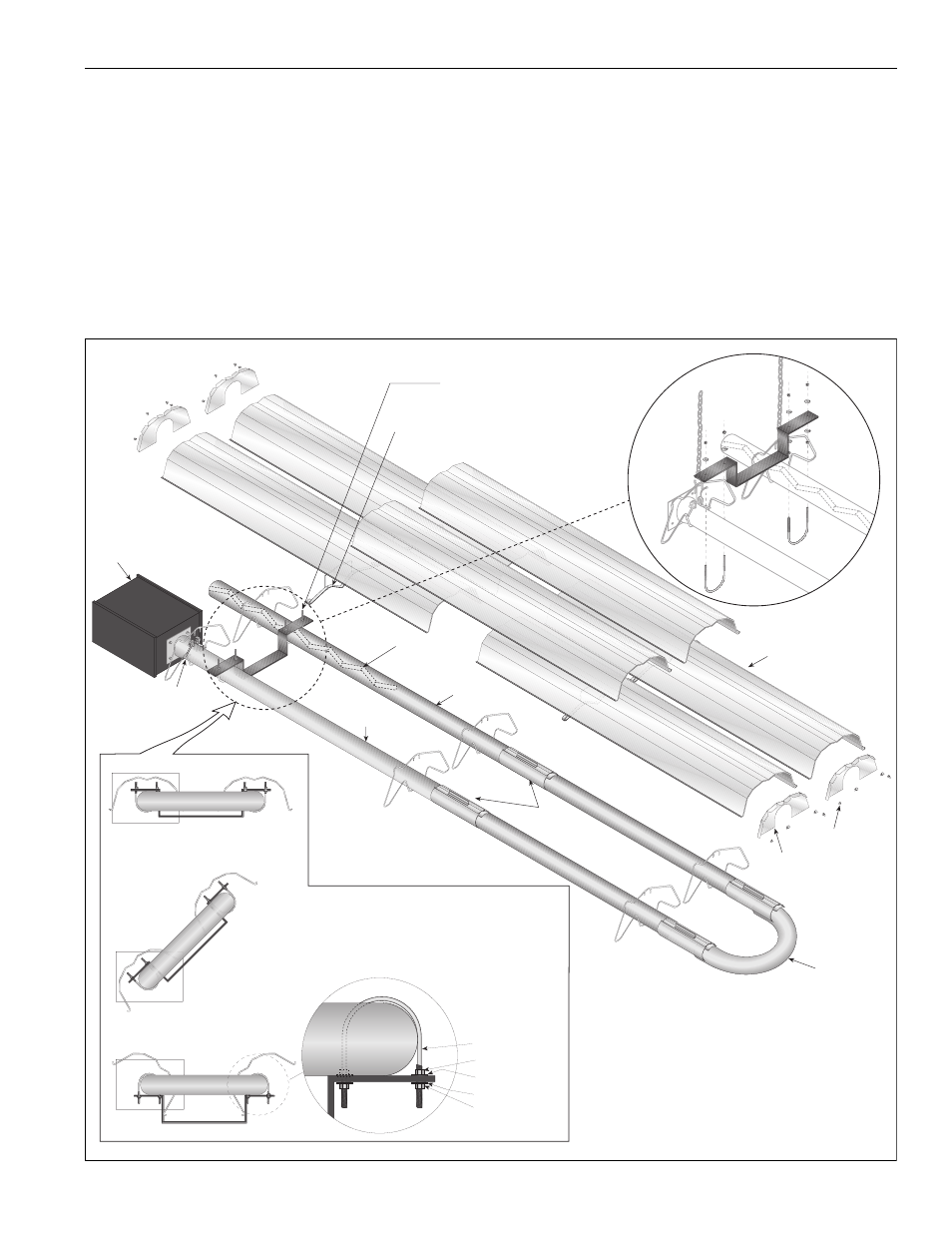
FIGURE 18: U-Tube Heater Assembly Overview
U-Tube
18" (457 mm)
Center to Center
U-Clips
Reflector
End Caps
Tight U-Bolt
4" (10 cm) U-Bolt,
secured to Burner Tube
with 1/4" (6 mm)
Lockwashers and
1/4-20 Hex Nuts
Loose U-Bolt
4" (10 cm) U-Bolt,
secured to Bracket with
1/4" (6 mm) Lockwashers
and 1/4-20 Hex Nuts on
top and bottom to
allow for tube expansion
and contraction
1
2
1
2
1
2
U-Tube, 45°
1
2
Burner
Reflector
(Turbulator
With Select
Models)
Tube Clamp
Package
Burner
Tube
Tube
U-Tube
Support Bracket
Reflector
Support
Couplings
U-Tube, Standard
U-Tube, Opposite 45°
Nut
Lock Washer
Lock Washer
Nut
U-Bolt