Raytherm - type h, Hydronic heating boilers, Model – Raypak RAYTHERM 962-1826 User Manual
Page 2
Catalog No.: 2000.24O
Effective: 04-15-10
Replaces: 12-01-07
Raytherm - Type H
Hydronic Heating Boilers
Model
11 3/4
14 1/2
5
A/2
A
L
1 1/8
COMBUSTIBLE FLOOR SHIELD
14
11 1/8
5 1/8
2 1/2
G
GAS
ELEC.
CONN.
27 3/4
C
J
B
11 1/4
6
32 1/2
(J-BOX)
(OPTIONAL)
H
IN
OUT
K
H - INLET
(OPPOSITE SIDE)
7-7/8
15-1/4
H - OUTLET
OPTIONAL ONE PASS
DRAFT HOOD
(OPTIONAL)
19 1/2
(OPTIONAL)
PUMP
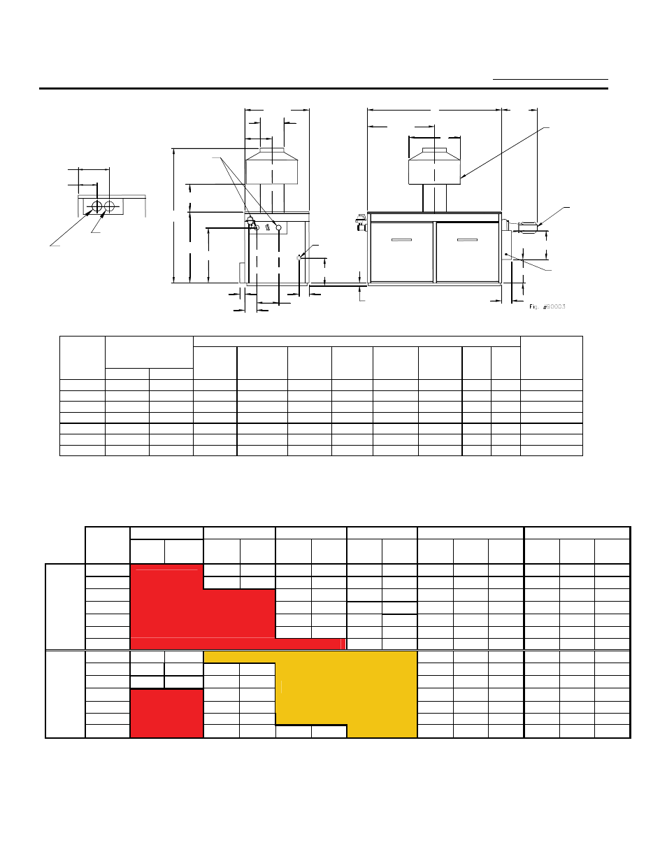
MODELS 962 THRU 1826
Dimensions
(Inches)
Approx.
MBTUH
Overall
Jacket
Gas
Water
Flue
Shipping
Model Natural
Gas Width
Height
Height
Conn.
Conns. Dia.
Weight
Size
Input
Output
A
B
C
G
H
J
K
L
(Lbs.)
H-962 961.7 788.6 52-3/8 76-1/8
(a) 33-1/2
1 2-1/2
(c) 23-5/8 14 28
705
H-1125
1124.7
922.0
59-1/4
78-1/8 (a)
33-1/2
1 (b)
2-1/2 (c)
23-5/8
16
32
745
H-1223
1222.5
1002.4
63-5/8
78-1/8 (a)
33-1/2
1 (b)
2-1/2 (c)
23-5/8
16
32
805
H-1336 1336.6 1096.0 68-5/8 80-1/8
(a) 33-1/2 1-1/4 2-1/2
(c) 23-5/8 18 36
875
H-1468 1467.0 1203.0 74-7/8 80-1/8
(a) 33-1/2 1-1/4 2-1/2
(c) 23-5/8 18 36
945
H-1631 1630.0 1336.6 81-1/8 83-1/8
(a) 36-1/2 1-1/4 2-1/2
(c) 23-5/8 18 36
985
H-1826 1825.6 1497.0 89-3/8 85-1/8
(a) 36-1/2 1-1/4 2-1/2
(c) 23-5/8 20 40
1035
NOTE: Ratings shown are for elevations up to 2,000 feet. For
elevations over 2,000, reduce ratings at the rate of 4% for each
1,000 feet above sea level.
(a) Add 1-1/8" to overall height for combustible floor shield option
(b) 1" or 1-1/4" contingent on boiler type or code requirements
(c) 3" NPT on single-pass option
(d) Propane input/output is 92% of standard values
Raypak, Inc. 2151 Eastman Avenue, Oxnard, CA 93030 (805) 278-5300 Fax (800) 872-9725 www.raypak.com
BOILER RATE OF FLOW AND PRESSURE DROP
10º ΔT 20º
ΔT 30º
ΔT 40º
ΔT
Minimum Flow
Maximum Flow
Model
No.
GPM
ΔP
FT
GPM
ΔP
FT
GPM
ΔP
FT
GPM
ΔP
FT
GPM
ΔP
FT
ΔT GPM
ΔP
FT
ΔT
H-962
80 8.8 53 3.8 40 2.2 40 2.2 38 90 11.0 18
H-1125
90 12.0 61 5.5 47 3.3 45 3.1 40 90 12.0 21
H-1223
76 7.0 51 4.0 51 4.0 40 90 12.5 22
H-1336
73 8.6 55 4.9 55 4.9 40 90 13.2 25
H-1468 80
11.0
61
6.4
61 6.4 40 90 14.0 27
H-1631
Exceeds Maximum Flow
90 14.8 68 8.3 68 8.3 40 90 8.3 30
TWO-
PASS
H-1826
76 10.8 76 10.8 40 90 15.4 34
H-962 157 6.1
90
2.1
18
200
9.7
8
H-1125 184 8.8 92 2.3
90 2.3 20 200 10.3 9
H-1223 200 11.0 100 2.9
90 2.4 22 200
11.0 10
H-1336 110
3.7
90
2.5
24
200
11.7
11
H-1468 120
4.5
90
2.7
27
200
12.2
12
H-1631 134
6.0
Less than Minimum Flow
90 2.8 30 200
13.0 13
ONE-
PASS
H-1826
150 8.0 100 3.7
90
3.0
33
200
14.7
15
NOTES:
•
Values represent maximum flows and pressure drops for closed heating systems
•
Maximum acceptable flow through heat exchanger tubes is 90 GPM (two-pass); 200 GPM (one-pass)
•
Single-pass heat exchangers are to be used only when flow rates exceed the allowable for two-pass