Warning – Ryobi AP13AK User Manual
Page 6
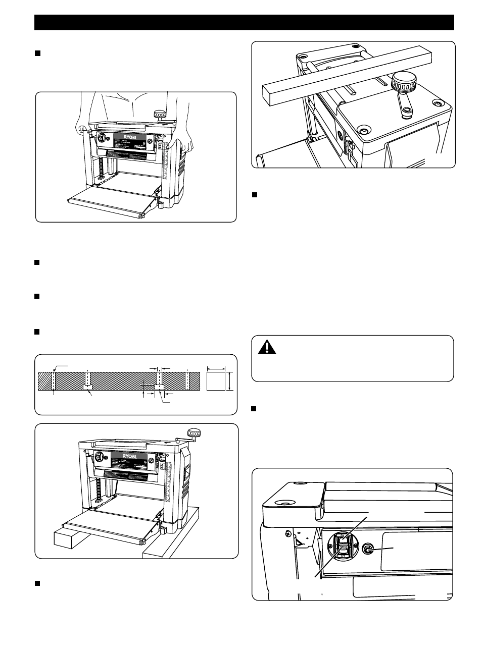
MOVING THE PLANER (Fig. 1)
The planer can be carried using the handles on either
side of the frame. Make sure the table extensions are
closed before moving the planer.
MOUNTING THE PLANER ONTO THE WOOD
BASE (Fig. 2a&2b)
When the planer is not mounted on a planer stand,
it is suggested that it be mounted onto two pieces of
timber. This will ensure maximum stability.
Choose two pieces of wood according to the sizes
shown on the figure below . Mount the planer onto
the wood surface.
Use four long, furnished screws to mount the planer
base onto the wood (Fig. 2a)
STOCK ROLLERS (Fig. 3)
Two rollers are built on top of the planer, providing
convenient handling of stock for consecutive cutting
operations. Stock placed on the top of the machine
can be easily pulled to the operator for planing.
ON / OFF SWITCH (Fig. 4)
Your Planer Thicknesser has a rocker style
switch with a removable locking key to prevent
unauthorised use. If you intend to be away from
the machine for a long period of time and there
is any chance of it’s use by others, especially
children, remove the locking key with the switch in
the OFF position. Store the locking key in a safe,
inconspicuous place in your workshop. To turn
the planer on, insert the locking key and turn the
switch to the ON position. The planer will then be
operable. To turn the planer off, turn the switch to
the OFF position. (Fig. 4)
Page 5
OPERATION
WARNING:
Always be sure the switch is in the off position
before connecting the planer to the power source.
CIRCUIT OVERLOAD SWITCH
The machine is provided with an overload switch
for overload protection. If an overload occurs, the
switch will pop out. If this happens, wait several
minutes and press the switch to reset the machine.
(Fig. 4)
On/Off Switch
Locking Key
Circuit Overload
Switch
On/Off Switch
Fig. 4
Fig. 1
2-Ø9
Mounting
Hole
Planer Base
Hole
15
m8 crew
Ш15
Ш9
50.8
50.8
Fig. 2b
Fig. 3
Fig. 2a