Iring diagram, Esting the unit – Rinnai RHFE-1510F User Manual
Page 13
W
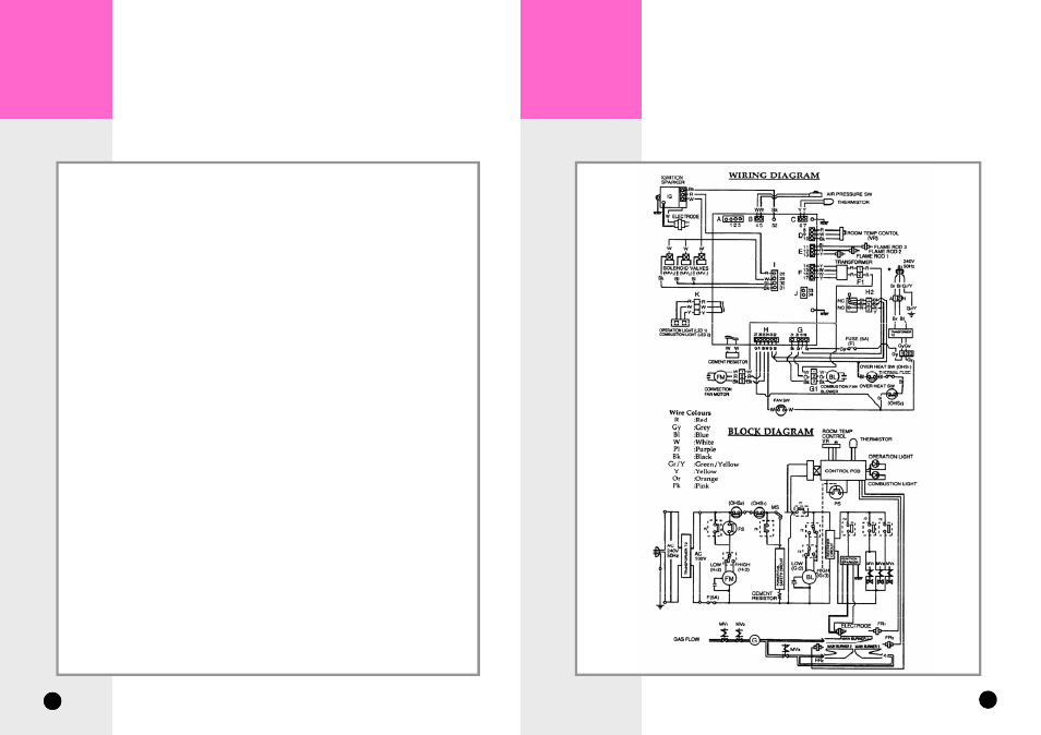
iring Diagram
T
esting the Unit
25
265
Purge air and sw arf f rom gas line.
x
Connect gas (1/2 inch BSP). Connection can be easily
reached from the top rear of the unit.
x
Check for escapes, using soapy water after turning gas on.
x
Remove fan filters.
x
Remove front covers, 2 screws at the bottom of lower
cover, 2 at bottom of upper cover.
x
Remove inner right hand cover (5 screws).
x
Remove test point screw, attach pressure gauge to test
point, (on solenoid valve). Turn power on.
(CAUTION: 240V inside unit).
x
Turn thermostat to ‘HI’, turn control to ‘ON’. Unit should ig-
nite within 10 seconds. (If unit does not ignite first time it
will spark again after 10 seconds).
x
If unit does not ignite, there may be air in the gas line. Turn
control ‘OFF’ then ‘ON’ again.
x
Check pressure compared to value on page 30, regulator
is factory set, and should be correct.
x
If pressure is incorrect, check supply before altering regula-
tor.
x
Turn control to ‘OFF’ position, remove pressure gauge and
replace test point screw.
x
Re-light unit, on ‘HI’ setting. Slide thermostat control slowly
towards the ‘LO’ position, the heater will modulate down,
then cut out. (Depending on the room temperature).
x
Turn the power off.
x
Replace the casing.
x
Turn power on.
x
Recheck operation.