Electric pole trimmer, Troubleshooting, Servicing pole trimmer – Remington 117535-01 User Manual
Page 8
8
110939
ELECTRIC POLE TRIMMER
®
For more information, visit www.desatech.com
TROUBLESHOOTING
OBSERVED FAULT
Motor does not run when you squeeze trig-
ger lever
Motor runs, but cutting blades do not move
Pole Trimmer smokes during operation
POSSIBLE CAUSE
1. Trigger lock button not pressed to release
trigger lever
2. Extension cord connection is loose
3. Household circuit breaker is tripped or
open line fuse
4. Bad motor brushes
5. Open wiring on Pole Trimmer
Pole Trimmer damaged. Do not use Pole
Trimmer
Pole Trimmer damaged. Do not use Pole
Trimmer
REMEDY
1. Push lock button forward and squeeze
trigger lever (see Starting the Pole Trim-
mer,
page 5)
2. Check cord connections
3. Check circuit breaker or line fuse
4. Call for Technical Service
5. Call for Technical Service
Call for Technical Service
Call for Technical Service
Note: For additional help, visit our
technical service web site at
www.de-
satech.com.
WARNING: Unplug Pole Trimmer from power source before servicing.
Severe injury or death could occur from fire, electrical shock, or body
contact with moving blades.
SERVICING POLE
TRIMMER
The Pole Trimmer is a double-insulated tool
and contains some parts that can only be
replaced with original parts by an Autho-
rized Service Center. Visit our Technical
Service web site at
www.desatech.com
or contact our Technical Service Department
at 1-800-858-8501 (English Only) for the
nearest Authorized Service Center.
The parts listed on pages 10 and 11 are
considered to be user replaceable. See Re-
placement Parts and Accessories
, page 9, for
information on ordering these parts.
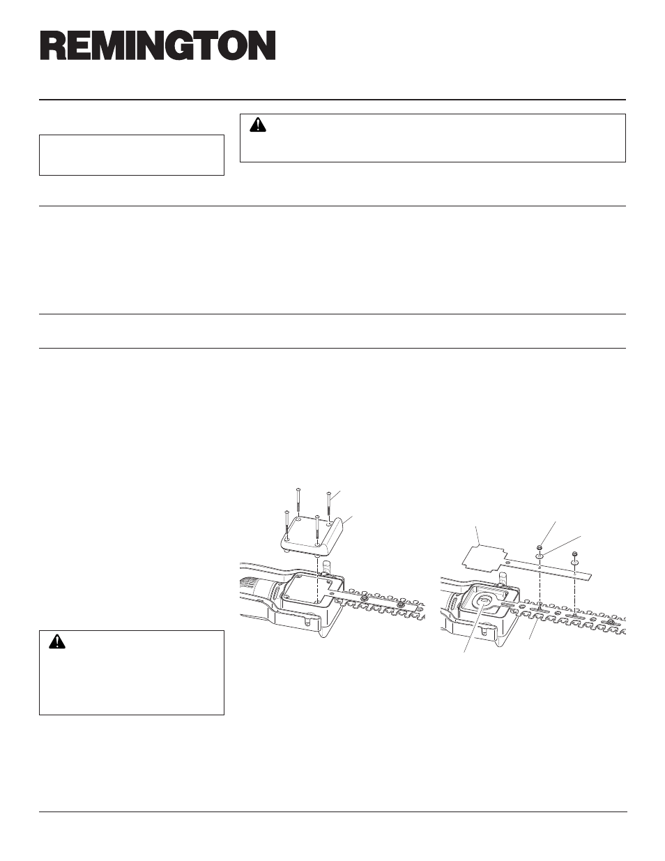
1. Unplug pole trimmer from power supply.
2. Place pole trimmer upside down on
workbench and remove the four (4)
bottom cover screws. Lift bottom cover
off (see Figure 17).
WARNING: To prevent serious
personal injury, wear gloves when
removing and installing the cut-
ter blades. Do not place fingers
or hands between blades where
they could get cut.
BLADE REPLACEMENT
3. Remove the two 5/16" nuts closest to
the power head and lift off cam cover
(see Figure 18). These parts will be
included with the new cutter blade and
will not be needed.
4. Rotate cam so that cam and cutter blade as-
sembly slot are aligned (see Figure 18).
Cover Screw
Bottom Cover
Figure 17 - Removing Bottom Cover from
Trimmer Head
5/16" Nut
Washer
Cam Cover
Figure 18 - Removing Cam Cover
Cam
Cutter Blade Assembly