Technical data, Valve description, Maintenance – Reliable Sprinkler RELIABLE Single Interlock Preaction System 6103060028 User Manual
Page 10: Resetting the single interlock preaction system
Technical Data
Reliable Single Interlock Preaction Systems, with asso-
ciated trim, sizes 4” (100mm), 6” (150mm) and 165mm
are rated for use at minimum water supply pressure of 20
psi (1,4 bar) and maximum supply pressure of 250 psi
(17,2 bar). Water supplied to the inlet of the valve and to
the pushrod chamber must be maintained between 40°F
(4°C) and 140°F (60°C).
The following list of technical bulletins pertains to valves
and devices that may be used in this preaction system:
Valve Description
1. Rated working pressure:
Valve & System - 175 psi (12,1 bar)
2. Factory tested to a hydrostatic pressure of 500 psi
(34,5 bar). (Valve only)
3. End and trim connections:
•
ANSI/AWWA C606 grooved inlet and outlet
•
Threaded openings Per ANSI B 2.1
4. Face to face dimensions:
•
4" (100 mm) — 14” (355 mm)
•
6" (150 mm) & 165 mm — 16” (406 mm)
5. Shipping weight:
6. Friction loss (Expressed in equivalent length of
Schedule 40 pipe, based on Hazen & Williams
Maintenance
Reliable Single Interlock Preaction Systems and asso-
ciated equipment shall periodically be given a thorough
inspection and test. NFPA 25, Inspection, Testing and
Maintenance of Water Based Fire Protection Systems,
provides minimum maintenance requirements. System
components shall be tested, operated, cleaned, and in-
spected at least annually, and parts replaced as re-
quired.
Resetting the Single Interlock Preaction
System
Refer to Figs. 2,
6, and 7.
1.
Close the main valve controlling water supply (Fig.
7) to the Deluge Valve and close off the air supply to
the sprinkler system at the air supply’s source.
2.
Close the pushrod chamber supply valve, valve A
(Fig. 7).
3. Open the
main drain valve, valve B (Fig. 7), and
drain system.
4. Open
all drain valves and vents at low points
throughout the system, closing them when flow of
water has stopped. Open valve D (Fig. 7). Note:
The above steps accomplish the relieving of
pres-
sure in the pushrod chamber of the Deluge
Valve.
5.
With Valve F (Fig. 7) open, push in the plunger of ball
drip valve, valve G (Fig. 7), to force the ball from its
seat, and drain any water in the alarm line.
6. With the Model B Manual Emergency Station, valve
D (Fig. 7
), open, push in and rotate the deluge
valve’s external reset knob
(#38, Fig. 6
) clockwise
until you hear a distinct clicking noise, indicating that
the clapper has closed. Note: The reset knob can
be rotated only after pressure in the pushrod cham-
ber has been reduced to atmospheric conditions (0
psig).
7.
Inspect and replace any portion of the sprinkler sys-
tem subjected to fire conditions.
8. Close valve F (Fig. 7). Activate a solenoid-release
pull station (Or other means of electric detection.) to
energize the solenoid valve(s). Silence any alarms
or audible tones on the releasing/control panel.
Open valve A (Fig. 7) to begin pressurizing the
push-rod chamber and its associated piping, while
simultaneously venting any entrapped air.
Note:
This venting of the air from the actuation piping is
very important to ensure proper system operation
and avoidance of falsely tripping the Deluge Valve.
10.
Deluge Valve
Reliable 510/511
Hydraulic Emergency Station (Model A)
Reliable 506
Solenoid Valve
Reliable 707
Mechanical Sprinkler Alarm
Reliable 612/613
Pressure Maintenance Device
Reliable 252
Air Compressor
Reliable 707/708
Electric Emergency Station
Reliable 707
Thermal/Smoke Detectors
Reliable 707
Fire Alarm Devices
Reliable 707
Waterflow Pressure Alarm Switch
Bailey & Mackey Ltd.
Model 1381V
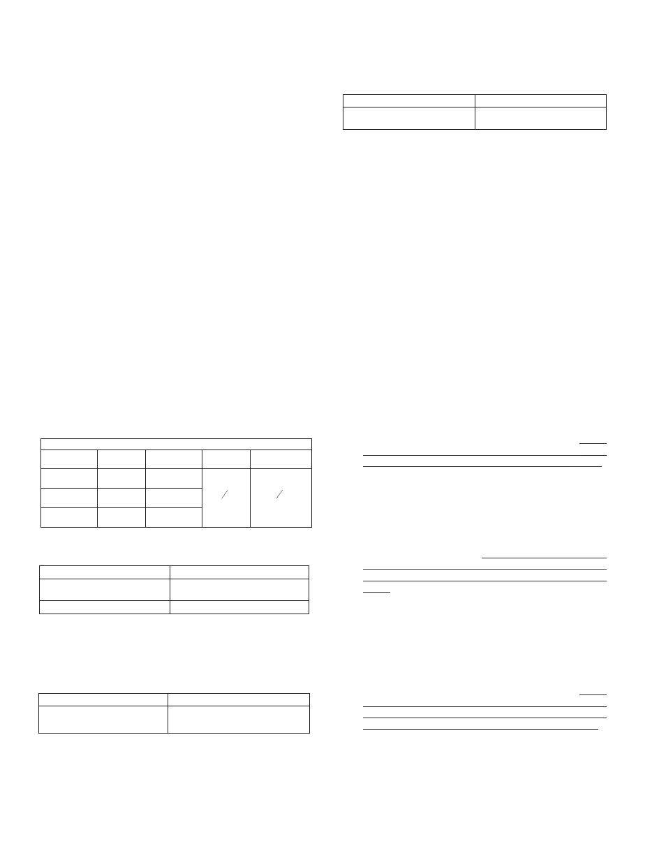
Groove Dimensions
Valve
Size
Outlet
Diameter
Groove
Diameter
Groove
Width
Outlet Face
to Groove
4"
(100mm)
4.500"
(114mm)
4.334"
(110)
3
8
"
(10mm)
5
8
"
(16mm)
165mm
6.500"
(165mm)
6.330"
(161mm)
6"
(150mm)
6.625
(168mm)
6.455"
(164mm)
Valve Size
Weight
4" (100 mm)
6" (150 mm) & 165mm
64 lb. (29 kg)
95 lb. (43 kg)
Valve Size
Color
4" (100mm)
6" (150mm)
Black
165mm
Red
formula with C=120 and a flow velocity of 15ft/sec
(4.6 m/sec)):
7. Installation position: Vertical
Valve Size
Equivalent Length
4" (100mm)
6" (150mm) & 165mm
14' (4.27 m)
29.4' (9 m)