Cs 20, Cs 20 l, Operating instructions – STIEBEL ELTRON CS 20 L User Manual
Page 10: Unit settings heat outputs, 1 unit description, 2 operation, 3 safety instructions
8421.01
10
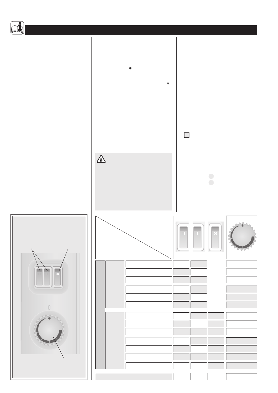
The most important
points in brief
Variable heat
outputs
2
Fan booster
(CS 20 L only)
3
Thermostatically
controlled
1
Frost protection with 750 W
ON
!
Heating with 750 W
ON
CS 20
Con
vection onl
y
CS 20 L
with fan
CS 20 L
ON
OFF
Heating with 1250 W
ON
Heating with 2000 W
ON
ON
Frost protection with 1250 W
ON
!
Frost protection with 2000 W
ON
ON
!
Heating with 750 W
ON
ON
Heating with 1250 W
ON
ON
Heating with 2000 W
ON
ON
ON
Frost protection with 750 W
ON
ON
!
Frost protection with 1250 W
ON
ON
!
Frost protection with 2000 W
ON
ON
ON
!
Fan only
ON
MAX
Unit settings
Heat outputs
depending on heat requirement
Switching the unit off
OFF
OFF
OFF
1. Operating instructions
for the user and the professional
1.1 Unit description
The CS 20 (L) is suitable for heating rooms
that are used infrequently, or to supplement
an existing heating system.
These units can be used as mobile free-standing
units with the feet fitted, or alternatively as wall
hanging units. As free-standing units they can
easily be used wherever heat is required quickly.
The heat requirement of the room should be
matched to the heat output of the unit.
When moving the unit it must only be held
using the recessed grips provided for this
purpose (6).
To heat the air, ambient air entering the unit
through the openings in the base of the unit
is heated, this then flows out by means of na-
tural convection, via the air outlet grille (4) at
the top.
In the case of the CS 20 (L), this process can
be assisted by using the integral fan to push
heat out through the separate outlet grille (5).
1.2 Operation
The operating controls are located within the
left hand side section of the unit.
Using the thermostat knob (1), the desired
room temperature can be selected between
approximately 5 °C and 35 °C.
The thermostat within the unit then keeps
the ambient air constantly at this set value, by
cycling the heating on and off for short periods.
Using the switches (2), three different heat
output levels can be selected (750 / 1250 /
2000 W, see table). This gives increased
economy by adapting to the prevailing heat
requirement.
Frost protection
If the unit is used as a frost protection
safeguard, the thermostat knob should be
turned anticlockwise to the end limit stop
and one of the two selector switches for
heat output must be in the ‘on’ position. The
thermostat automatically switches on the
heating if the room temperature falls to
approximately 7 °C.
In the case of the CS 20 (L), the fan can be
switched on in all settings using the third
switch (3).
To take the unit out of operation, all switches
must be switched to the OFF setting.
1.3 Safety instructions
The appliance must not:
– Be operated in areas which are subject
to the risk of fire or explosion due to
chemicals, dust, gases or vapours;
– Be operated in the immediate vicinity of
pipes or containers which carry or
contain combustible or potentially explo-
sive substances;
– Be operated, at less as the minimum
clearance distances advised.
•
Under no circumstances must the unit be
operated if work such as the laying,
sanding, sealing, cleaning with petrol, and
maintenance (spraying, waxing) of floors
and the like is being carried out in the
room where the unit is installed.
•
The wall surface and the air outlet grid of
the unit can heat up to temperatures of
over 85°C. For this reason, no objects of
any kind must be placed on the unit,
leaned against it, or put between the
heating unit and the wall (for example to
dry the washing).
In addition, no combustible, flammable, or
heat insulating objects or materials such as
washing, blankets, magazines, containers
holding floor wax or petrol, spray cans and
the like, should be placed in the immediate
vicinity of the unit. Danger of fire!
•
A For objects of all kinds, such as for
example furniture, drapes, curtains and tex-
tiles or other flammable or non-flammable
materials, the following minimum distances
from the unit, particularly from the air
outlet grille, must be observed:
In front of the air outlet grille
⇒
500 mm
Above the air outlet grille
Overhang a <200 mm
⇒
250 mm
Overhang a >200 mm
⇒
500 mm
Side of unit
⇒
100 mm
Rear of unit
⇒
20 mm
The hot air m
The hot air m
The hot air m
The hot air m
The hot air must be ab
ust be ab
ust be ab
ust be ab
ust be able to exit
le to exit
le to exit
le to exit
le to exit
unimpeded!
unimpeded!
unimpeded!
unimpeded!
unimpeded!