Assembly – RIDGID AC99402 User Manual
Page 9
9
ASSEMBLY
MOUNTING OTHER BRANDS
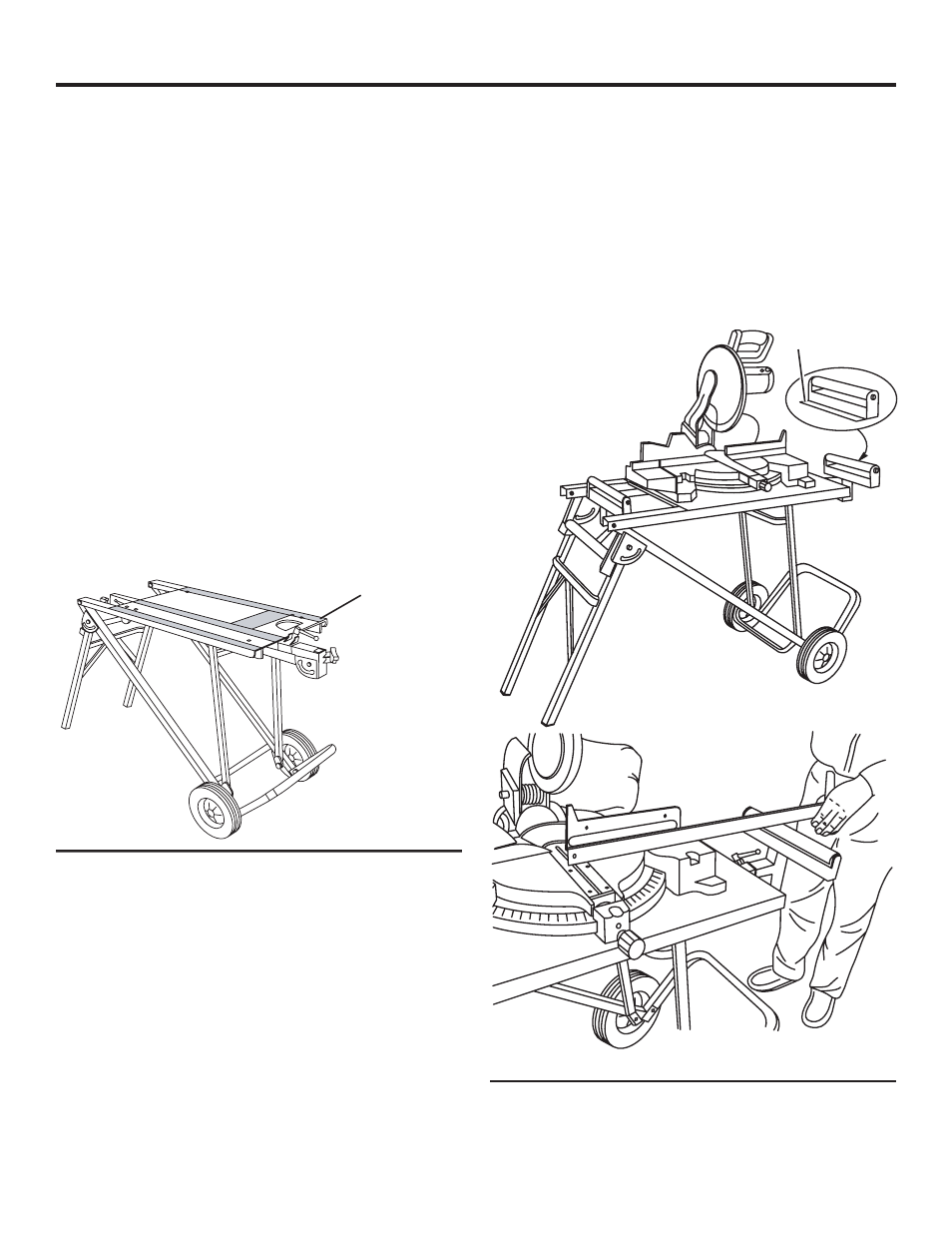
See Figure 8.
NOTE: Other brands of miter saws (not RIDGID miter saws)
will require additional 5/16 in. mounting holes to be drilled.
See instructions below.
n
Locate the following parts:
Hex Bolts, M6 x 40mm (4)
Flat Washers, M6 (4)
Fender Washers, M6 (4)
Lock Nuts, M6 (4)
CENTER THE MITER SAW ON THE WORK-
STAND
Check and make sure
n
The front of the miter saw faces the front of the
workstand as shown above.
n
The miter saw is mounted so the workpiece is positioned
in line with the roller assemblies as shown above.
n
The mounting hardware will not interfere with the sliding
table frame members underneath table. Shaded areas on
table in figure 8 show locations that mounting hardware
may interfere with folding/locking mechanisms. Be sure
to position miter saw outside of these areas.
n
Mark the mounting hole(s) location. Remove miter saw.
DO NOT DRILL
HOLES IN
SHADED AREAS
n
Drill 5/16 in. mounting holes.
n
Reposition the miter saw on the workstand.
n
Slide flat washer on hex bolt and place through miter
saw and workstand. The larger fender type flat washer
can be placed on the bottom or top of the miter saw.
Certain mountings will require this washer to be placed
on top of the miter saw in order to provide clearance
with the frame. On some miter saws using mounting
position “C”, it is necessary to mount the hex bolt and
flat washer from the bottom side of the table on the rear
of the miter saw to allow clearance with the frame when
folding the stand in the upright storage position.
n
Slide a flat washer on hex bolt and “finger tighten” using
lock nut.
n
Repeat above steps for the other three mounting holes.
n
Tighten all lock nuts.
MOUNTING AND ALIGNING ROLLER ASSEMBLY
See Figure 9.
n
Insert roller assembly into each extension bar.
NOTE: Make sure length stop is positioned towards miter
saw.
NOTE: Load capacity of each roller is 100 pounds
maximum.
n
Place a straight edge on the miter saw table and adjust
roller assembly to table height.
LENGTH
STOP
Fig. 9
Fig. 8