Operating tips for active line tracing – RIDGID SR-60 User Manual
Page 19
Ridge Tool Company
Elyria, Ohio
U.S.A
www.seektech.com
17
SeekTech SR-60
Current and Signal Angle Reading
The Current Strength (
) and Signal Angle
indicator (
) in the upper right corner of the screen
will display the current detected on the traced line, in
milliamps, when the computed angle to the center of
the detected field is less than 35° and the SR-60
crosses the center of the field.
When moving across the center of the field the
current display will retain the displayed current value
until the guidance arrows reverse again, at which
point the display will be updated. The update occurs
whenever the guidance arrows reverse.
When the angle to the center exceeds 35°, the Signal
Angle indicator will again replace the Current
indicator, and the display will show the computed
angle to the center of the detected field.
Clipping (Tracing Modes)
Occasionally the Signal Strength will be strong
enough that the receiver will be unable to process the
whole signal, a condition known as “clipping”. When
this occurs, a warning symbol
will appear on
the screen. It means that the signal is particularly
strong. If clipping persists, remedy it by increasing
the distance between the antennas and the target
line OR by reducing the strength of the current from
the transmitter.
Note: Measured Depth Display is disabled
under clipping conditions.
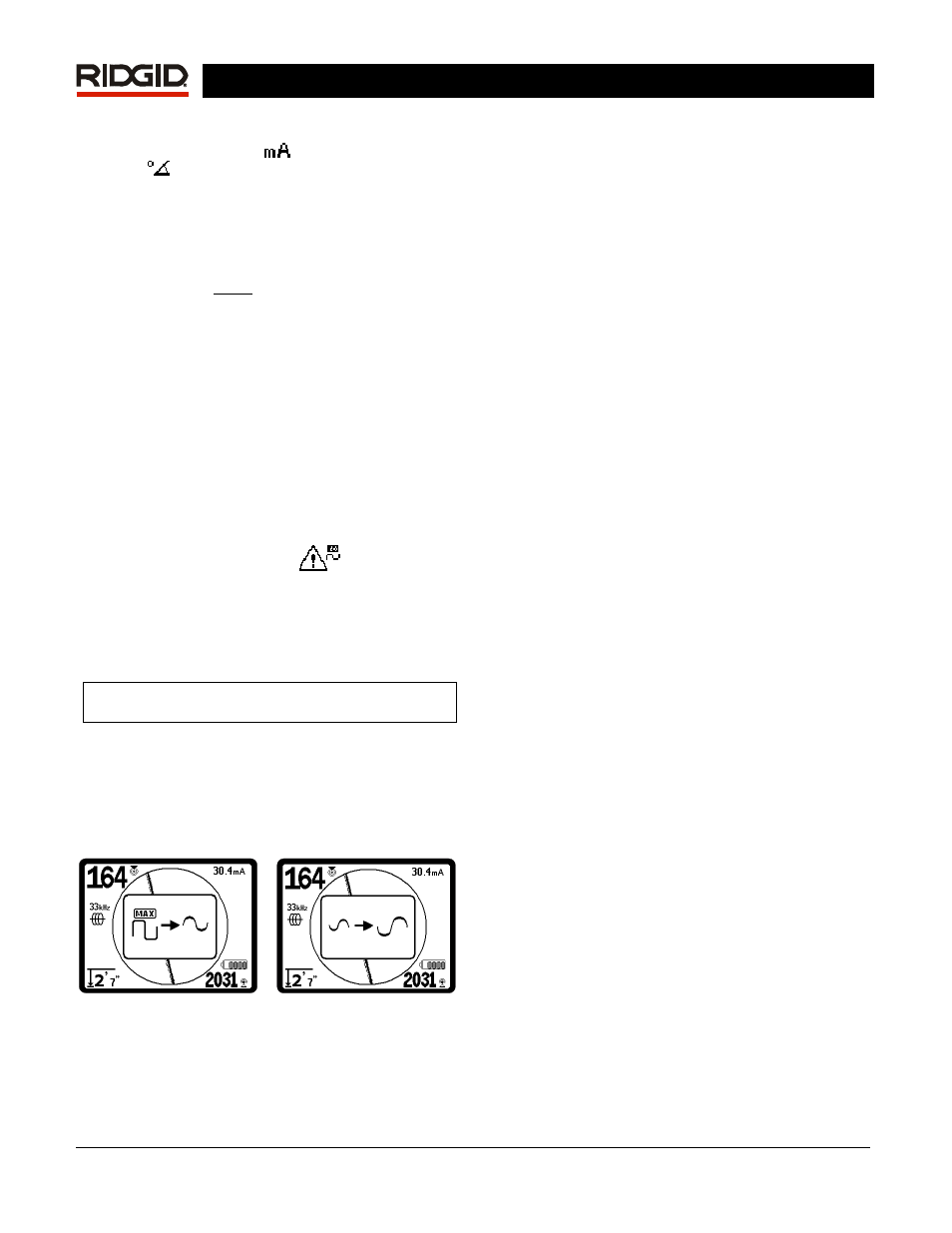
When clipping occurs, the SR-60 will automatically
attenuate the signal to dampen it. When the signal
strength received falls below the clipping threshold,
the attenuation stops automatically. The SR-60
screen will indicate the starting of attenuation and the
stopping of attenuation by showing these images:
Figure 25: Attenuation On
Figure 26: Attenuation Off
Operating Tips for Active Line
Tracing
1. The SR-60 quickly identifies distorted fields. If the
guidance arrows are centered on the screen, and
the Trace Line is not centered (or if the Proximity
Signal number and Signal Strength are not
maximized), then distortion is creating a complex
non-circular field. This is also reflected by the
Tracing line dissolving, or growing unfocused in a
cloudy pattern proportional to the distortion
detected.
2. To improve the tracing circuit:
a. Move the ground stake position away
from the line to be traced.
b. Use a larger ground contact surface
(such as a shovel blade).
c. Make sure that the line is not commonly
bonded to another utility. (Undo common
bonds only if safe to do so).
d. Try changing the frequency used.
e. Move the transmitter to a different point
on the line, if possible. Try locating from
the other direction along the line, for
example.
3. Circling the last location of a clear signal at a
distance of about 20 feet (6.5 m) can clarify if the
distortion is coming from a local turn or tee in the
line, and enable the operator to again pick up the
line nearby.
4. If the Tracing Line will not center or if it moves
across the screen erratically, then the SR-60 may
not be receiving a clear signal. The Measured
Depth and the Proximity Signal may also be
unstable under these circumstances.
a. Check the transmitter to be sure that it is
operating and well grounded. Good
connection and good grounding can
remedy low current problems.
b. Test the circuit by pointing the lower
antenna at either transmitter lead. If a
strong signal is not shown, improve the
circuit.
c. Check that the SR-60 and transmitter are
operating on the same frequency.
d. Try a higher frequency, until the line can
be picked up dependably. Using lower
frequencies can overcome bleed-over
problems. Higher frequencies can