At-series heating unit, End view front view – Roberts Gorden Combat AT-236 User Manual
Page 2
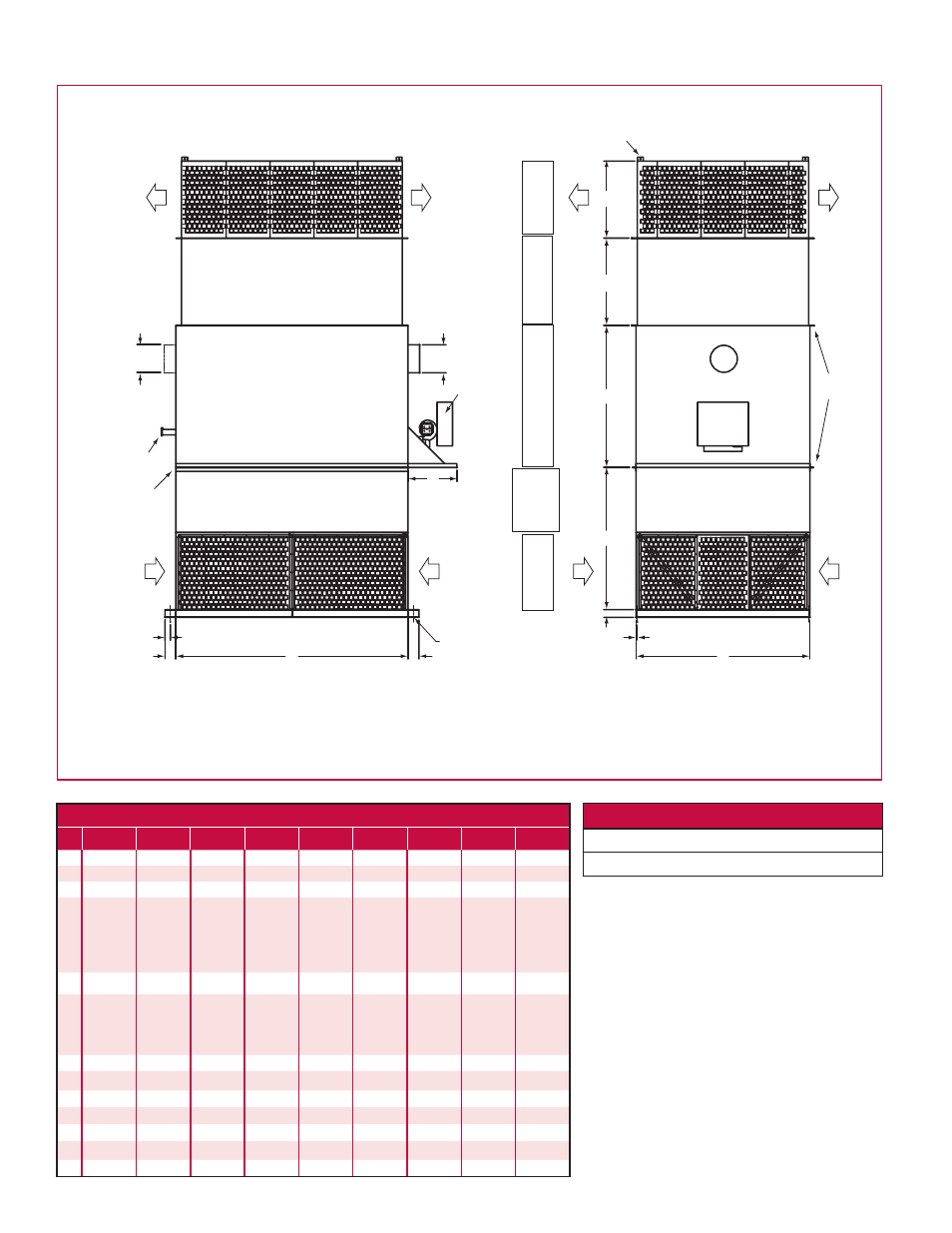
A
M
M
B
N
L
C
G
D
H
F
F
SPLIT FOR
SHIPMENT
INSPECTION
AND RELIEF
PORT
E
K
LIFTING
ANGLES
J
L
CONTROL
PANEL
DA
DA
RA
RA
RA
RA
DA
DA
END VIEW
FRONT VIEW
DISCHARGE
PLENUM
EXTENSIONS (OPTIONAL)
HEA
T EXCHANGER SECTIO
N
PROPELLER FAN / INLET
SECTION
INLET PLENUM
AT-Series Heating Unit
2
IMPORTANT NOTES:
•
All dimensions are in inches.
•
All dimensions are subject to change
without notice.
•
Due to height of unit, additional support is
recommended on top of the unit.
•
Dimension "F" is flue diameter. Flue located
on left side of unit for 1,000 MBH heat
exchanger and smaller; flue located on right
side of unit for 1,250 MBH heat exchanger
and larger.
•
Dimensions "D" and "F" may vary depending
on heat exchanger size (ex. 45 = 450 MBH
heat exchanger).
LEGEND
DA = Discharge Air
RA = Return Air
DIMENSIONS
AT-136 AT-148 AT-154 AT-236 AT-242 AT-248 AT-254 AT-260 AT-272
A
60
72
85
90
100
116
145
160
165
B
50
60
72
50
55
60
72
84
90
C
75
75
86
60
66
66
72
72
76
D
53
53
65
53
75 - 53
100 - 53
125 - 72
75 - 53
100 - 53
125 - 72
150 - 72
175 - 72
90
96
96
E
35
35
35
35
35
35
35
35
35
F
45 - 6
75 - 6
100 - 8
45 - 6
75 - 6
100 - 8
45 - 6
75 - 6
100 - 8
125 - 10
45 - 6
70 - 6
100 - 8
75 - 6
100 - 8
125 - 10
75 - 6
100 - 8
125 - 10
175 - 12
175 - 12
225 - 12
300 - 14
300 - 14
450 - 16
300 - 14
450 - 16
G
3
3
3
3
3
3
4
4
4
H
24
24
36
24
30
30
36
36
40
J
48
48
48
48
48
48
48
48
48
K
.75
.75
.75
.75
.75
.75
.75
.75
.75
L
.75
.75
.75
.75
.75
.75
.75
.75
.75
M
6
6
6
6
6
6
6
6
6
N
3
3
3
3
3
3
3
3
3