Warning, Trimmer assembly – Remington BS1812A User Manual
Page 8
8
www.desatech.com
TRIMMER ASSEMBLY
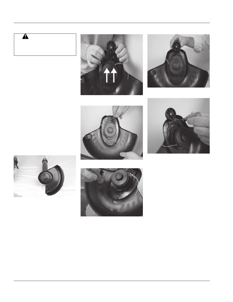
ASSEMBLING TRIMMER/EDGER
Figure 4 - Placing cutting guard over cut-
ting head
Figure 5 - Slide cutting guard forward
ATTACHING CUTTING GUARD
AND EDGING WHEEL
1. Remove
fi ve mounting screws taped to
underside of cutting guard.
2.
Place cutting guard over spool housing at
a slight angle. Push guard back depress-
ing tabs toward front of cutting guard.
(See fi gure 4). Drop back of cutting guard
into place.
3.
Slide cutting guard forward. (See fi gure
5)
4. Insert mounting screw into hole near-
est tabs in cutting guard. Tighten screw
fi rmly. (See Figure 6)
5.
Insert two mounting screws into holes at
back of cutting guard. (See Figure 7)
6.
Place edging wheel over remaining two
screw holes at front of cutting guard.
Attach edging wheel using two mounting
screws. (See Figures 8 and 9)
FPO
Figure 7 - Insert two mounting screws
FPO
Figure 6 - Insert mounting screw
Figure 8 - Placing edging wheel over
screw holes
FPO
Figure 9 - Attaching edging wheel
FPO
Do not operate trimmer/edg-
er without guard or handle
in place.
WARNING: